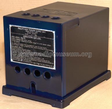
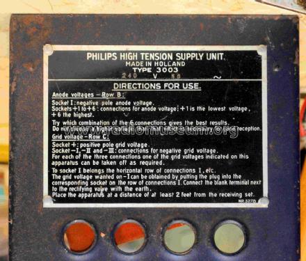
High Tension Supply Unit 3003
Philips Australia
- Pays
- Australie
- Fabricant / Marque
- Philips Australia
- Année
- 1928
- Catégorie
- Alimentation/stabilisateur de tension ou batterie ou chargeur
- Radiomuseum.org ID
- 337033
Credit Marcus Chick.
Credit Marcus Chick.
Credit Marcus Chick.

Credit Marcus Chick.
Credit Marcus Chick.
Cliquez sur la vignette du schéma pour le demander en tant que document gratuit.
- No. de tubes
- 2
- Gammes d'ondes
- - sans
- Tension / type courant
- Alimentation Courant Alternatif (CA) / 240 Volt
- Matière
- Boitier métallique
- De Radiomuseum.org
- Modèle: High Tension Supply Unit 3003 - Philips Australia
- Forme
- Modèle de table générique
- Remarques
-
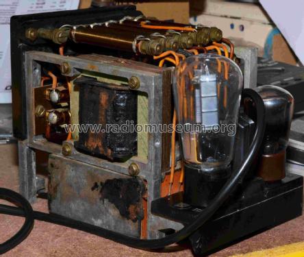
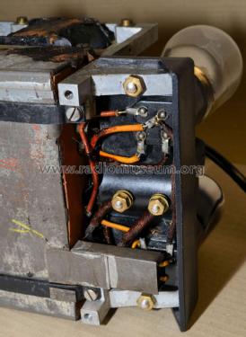
Philips AC powered, combined "B" & "C" power supply.
"B" Voltage up to 200 by means of six positive taps.
"C" Voltage up to 40 on any of three sets of taps.Made in Holland.
See also the Dutch version.
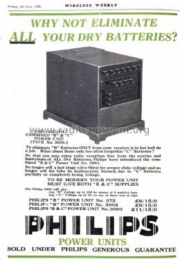
- Prix de mise sur le marché
- 11.75 AUS £
- Littérature
- Wireless Weekly (Australia) (Jun 1, 1928, Page 2.)
- Auteur
- Modèle crée par Gary Cowans. Voir les propositions de modification pour les contributeurs supplémentaires.
- D'autres Modèles
-
Vous pourrez trouver sous ce lien 915 modèles d'appareils, 716 avec des images et 425 avec des schémas.
Tous les appareils de Philips Australia
Contributions du forum pour ce modèle: Philips Australia: High Tension Supply Unit 3003
Discussions: 1 | Publications: 1
Modern Radio Equipment
Eliminating “B and C Batteries with One-Power Unit.
(By the Technical Dept., Philips Lamps Australasia, Ltd.)
The advantages of incorporating a “C” supply unit in a “B” eliminator are more than sufficient to justify the combination, as employed in the Philips type 3003 Power Unit.
Now that the necessity for using a power valve in the last audio stage has been fully realised, greater expenditure has been entailed when “C” batteries are employed, in order to obtain the comparatively high bias voltages required.
The 3003 will give up to 40 volts of negative bias for three separate stages if required, and tappings at every few volts make for exact adjustment.
A further advantage of the “B” and “C” eliminator is that, despite line voltage variation, the proportion of “C” bias to plate voltage remains constant. This would not be the case if “C” bias were independently obtained, and poor reproduction would be the result.
Many “B” and “C” units have been incorporated in receivers using a voltage divider, or Potentiometer, across the output from the “B” power unit. The “A” minus terminal was connected to a point, so placed from the negative end, that the drop in voltage from this “A” minus point to
the negative furnished a “C” potential to the power tube. This type of unit had the disadvantage that, besides lowering the plate voltage available, it tended towards bad regulation, and, although an increase in plate current theoretically produces a corresponding increase in “C” bias, the resistance of the rectifier and filter counteract this. Sufficient voltage was not available at the time when it was necessary to correct the abnormal plate current. Using this type of unit, “blasting” was generally encountered, and for this, there was no apparent remedy, except by reducing the audio input to the power tube.
In the design of type 3003, the troubles mentioned have been overcome by the arrangement in which the “C” bias potential is supplied from a separate thermionic rectifying unit.
This unit consists of a rectifying valve type, 3006, the filament supply for which is obtained from a winding on the main transformer.
The plate supply is obtained in a very novel manner, namely, the filament winding mentioned is connected to the plate end of the high voltage winding for the “B” unit. This means that the current flows into the “C” unit only when the plate end is negative, the cycle in which no current flows to the plate of the “B” unit rectifier. From the rectifier, the “C” current flows through extremely high resistances, which, in combination with condensers, perform the necessary smoothing.
As the maximum value of the current is 0.6 mA, no inductances are necessary for filtering. The resistances mentioned also cause a potential drop, and the voltage maintained across the tapped potential divider is 40 volts which, is necessary for the “C” bias. A further 2 mF condenser is connected from each individual “C” minus tap to the “B” minus terminal of the eliminator, which, when the eliminator is in use, is connected through the “A” battery to the “C” plus. This does not reduce the overall “B” voltage of the Philips 3003, which is identical to that of the type 3002, and the regulation is as good as that obtained from B batteries.
The operation of the unit is delightfully simple, “B” power being obtained from six different positive taps, which give a variety of potentials, not definitely marked on account of the variation according to the load. It is a matter of a few seconds only to test each of the taps, for the correct value, and after a little experience with the unit, the values can be gauged fairly accurately.
“Motor Boating.”
This phenomenon, which may be identified by a foreign noise, somewhat like that produced by the exhaust of a motorboat, is a sign that the audio amplifier is nearing the oscillation point.
The effect is generally produced by either the use of large core, high inductance transformers, or a combination of one of these and a resistance-coupled unit; or, further, two or more resistance-coupled units. This condition is accentuated by the use of run-down high resistance “B” batteries, or, in some cases a badly designed “B” battery eliminator.
The more perfectly constructed the amplifier the greater is the tendency to “motor-boat.”Thus in the construction of the Transformer special precautions were taken to eliminate the chance of this happening. It is the only transformer that safeguards the amplifier from this drawback.
With a view to alleviating the trouble, the manufacturers introduced into the construction of their power units also, features that had the effect of reducing the chance of “motor-boating.” This consisted of resistances in each of the “C” negative taps.
These resistances are of very high value (about one hundred thousand ohms) and, as no current should normally be flowing in the grid circuit, there is of course no drop in the potential. The action of these resistances is really to create a “Loss” in the grid circuit, which dampens it to such an extent that audio oscillation in the amplifier is practically impossible.
“Motor-boating” can also be accentuated by a high resistance rectifier or filter in a B power unit. However, the trouble may generally be overcome in a Philips 3002 or 3003 unit by connecting the “B” plug from the first audio stage into the third or fourth positive taps. This indirectly places a high resistance in the plate lead, the negative side of which is connected through a 2 mF condenser to negative “B”, thus bypassing the audio current to "A” negative without passing through the source of supply.
A. C. Hum or Ripple.
A.C. Hum, commonly known as "ripple” is very apparent in the older types of “B” and “C” eliminators, but by the special arrangement of the grid bias element in the Philips unit, the slightest ripple may be absolutely eliminated when the audio tubes are correctly biased. This is due to the fact that the correct bias will neutralise any ripple which exists in the plate supply. This holds good for all types of tubes irrespective of their impedance or amplification values.
Marked “C” Voltages.
A feature of the 3003 Power Unit is that the various “C” bias taps are marked with their respective values. This enables the average set owner, without testing instruments, to determine the "B” voltage required.
After consulting the leaflets supplied with every tube which gives grid bias requirements, the amount of “C” potential required is connected. The “B” plug is then varied until the best signals are received. At this point, the plate voltage will approximately correspond with that shown on the chart for the particular value of bias is applied. The marked values of the various "C” taps will remain constant during the whole normal life of the unit, irrespective of the load on the supply.
Thus it will be evident that the combination of "B” and “C” supplies in the one power unit as introduced by Philips has mutual benefits and many individual advantages. Certainly the
use of one unit for both purposes spells super-convenience to the set owner, who uses a battery-eliminating device of this kind.
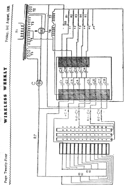
T1—Transformer primary.
T2—506 Rectifying Valve, filament winding.
T3 and T4—506 Rectifying Valve, plate supply winding.
T 5—3006 Rectifying Valve, filament winding.
T 6 and T7—Smoothing chokes for B power unit.
R1—Resistance for plus 1 tap B unit.
R2—Resistance for plus 2 tap B unit.
R3—Resistance for plus 3 tap B unit.
R4—Resistance for plus 4 tap B unit.
Rs—Resistance for plus 5 tap B unit.
R6—Resistance which is in series with
R1 across B supply output to keep the no-load voltage down.
R7—Resistance in C supply to reduce potential, also acting as part of the filter in conjunction with condenser C8 and C2.
R8 and R9—Potentiometer for varying C potential.
R10 —Resistance in minus C1 tap.
R11 —Resistance in minus C2 tap.
R12—Resistance in minus C3 tap.
C1, C4, C11—Main smoothing condensers.
C9, C10, C12, C13, C14—Condensers across B plus taps.
C5, C6, C7—Condensers across three minus C taps.
C3—Condenser from plus C tap to B minus by-passing A battery.
Wireless Weekly Aug 3, 1928, Pages 23 & 24.
Gary Cowans, 02.Apr.22