- Pays
- Pays-Bas
- Fabricant / Marque
- Philips; Eindhoven (tubes international!); Miniwatt
- Année
- 1954/1955
- Catégorie
- Radio - ou tuner d'après la guerre 1939-45
- Radiomuseum.org ID
- 114083


From Pieter Deckok site, with permission.

From Pieter Deckok site, with permission.


Cliquez sur la vignette du schéma pour le demander en tant que document gratuit.
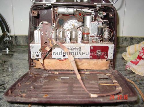
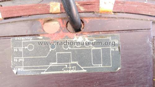
- No. de tubes
- 6
- No. de transistors
- Semi-conducteurs
- Selengleichrichter
- Principe général
- Super hétérodyne avec étage HF; FI/IF 452 kHz; 2 Etage(s) BF
- Circuits accordés
- 6 Circuits MA (AM)
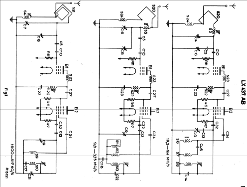
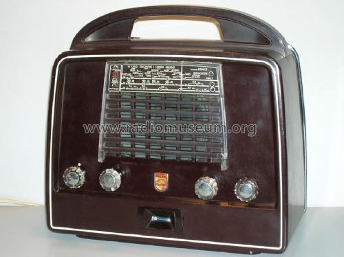
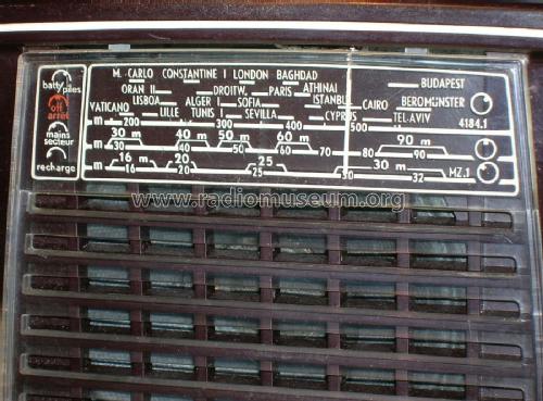
- Gammes d'ondes
- PO et 2 x OC
- Tension / type courant
- Secteur et Piles (tous types). / AC 110; 150; 220 / 2 x 1,5 & 2 x 67,5 Volt
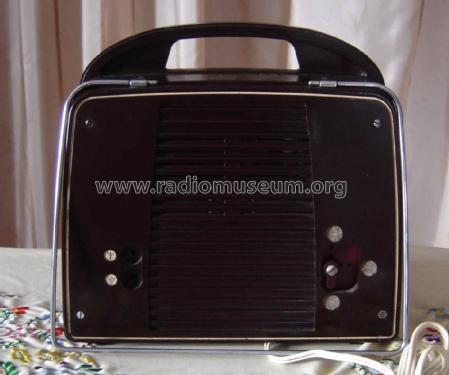
- Haut-parleur
- HP dynamique à aimant permanent + bobine mobile / Ø 5 inch = 12.7 cm
- Puissance de sortie
- 0.3 W (qualité inconnue)
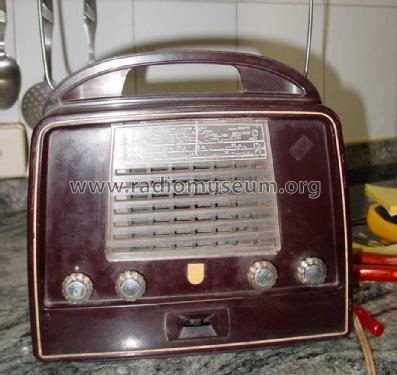
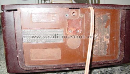
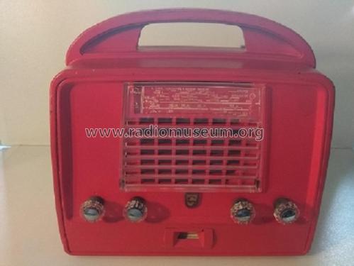
- Matière
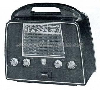
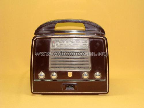
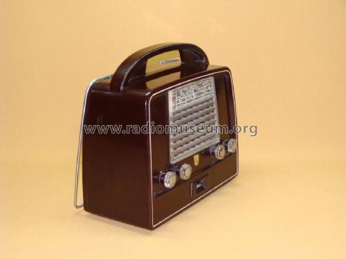
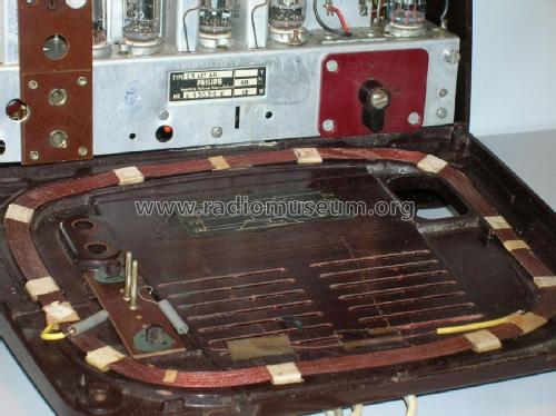
- Boitier en bakélite
- De Radiomuseum.org
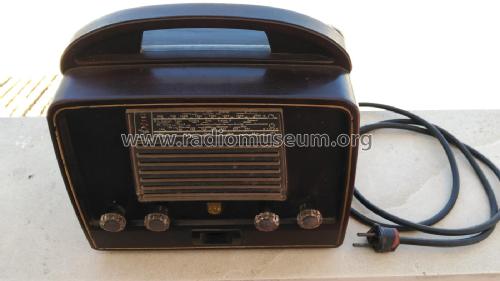
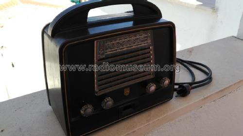
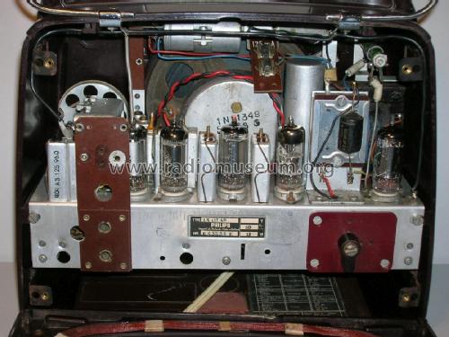
- Modèle: LX437AB - Philips; Eindhoven tubes
- Forme
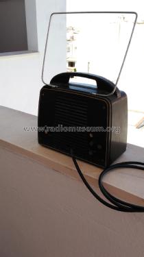
- Portative > 20 cm (sans nécessité secteur)
- Dimensions (LHP)
- 260 x 250 x 120 mm / 10.2 x 9.8 x 4.7 inch
- Remarques
-
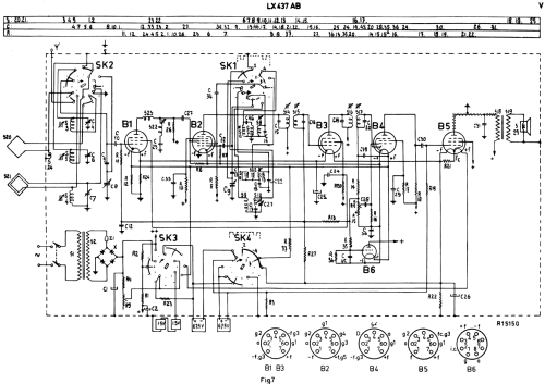
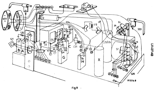
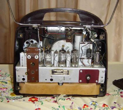
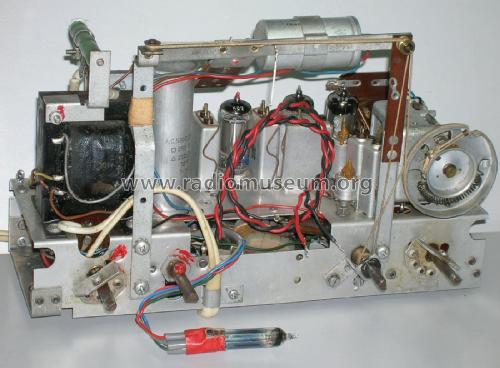
The Philips receiver LX437AB features a tuned rf preamplifier with aperiodic coupling to the mixer stage.
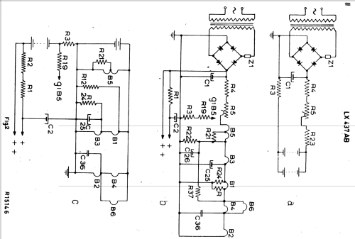
Power consumption from AC mains: 17W. Selenium rectifier bridge.
- Prix de mise sur le marché
- 1,950.00 PTE
- Littérature
- -- Original prospect or advert
- Schémathèque (1)
- -- Original-techn. papers.
- Auteur
- Modèle crée par Mario Coelho. Voir les propositions de modification pour les contributeurs supplémentaires.
- D'autres Modèles
-
Vous pourrez trouver sous ce lien 5277 modèles d'appareils, 4424 avec des images et 3459 avec des schémas.
Tous les appareils de Philips; Eindhoven (tubes international!); Miniwatt
Collections
Le modèle fait partie des collections des membres suivants.
Contributions du forum pour ce modèle: Philips; Eindhoven: LX437AB
Discussions: 1 | Publications: 3
Hi.Radiophiles, It came to me for repair/recover one portable radio LX 437 AB.I don't have its schematic,but supose may be similar to model LI 437/AB.My problem is that I don't have the correct filament tensions when switched to the mains.As a matter of fact,the wires that should conect to the batteries have been cut so I can not test it with the batteries once they are not there.And some help would be very welcome if somebody could explain me the wiring of the tubes filaments,once I find very dificult to understand the complexity of the switch wiring together with the dificult access to components and lack of data of voltages.
May I wish to all members and their families a Merry Christmas and a Happy new Year with greetings from our Sunny Algarve!
Antonio Barros-Regada, 21.Dec.13