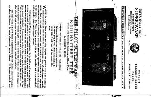
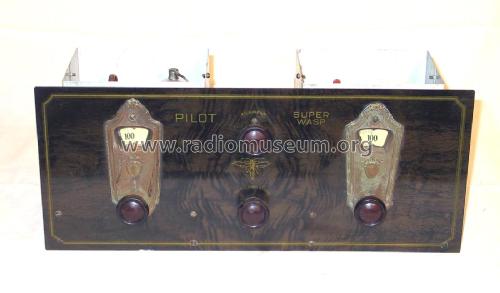
Super Wasp K-110
Pilot Electric Mfg. Co. (Radio Corp.); Brooklyn (NY)
- Produttore / Marca
- Pilot Electric Mfg. Co. (Radio Corp.); Brooklyn (NY)
- Anno
- 1927
- Categoria
- Kit, scatola di montaggio (parti sfuse e istruzioni o solo istruzioni di montaggio)
- Radiomuseum.org ID
- 51957
-
- alternative name: Pilot Radio & Television || Pilot Radio and Tube || Pilot Radio Corporation


Lafayette Catalog 1931 Page 62
Radio-Craft 07-1929


7

Clicca sulla miniatura dello schema per richiederlo come documento gratuito.
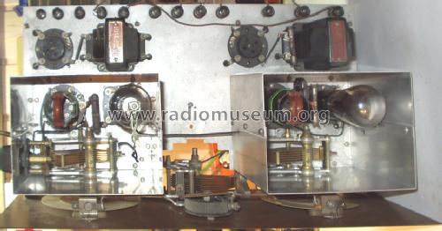
- Numero di tubi
- 4
- Principio generale
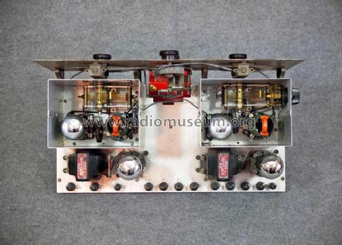
- A reazione (con rigenerazione); 2 Stadi BF
- N. di circuiti accordati
- 2 Circuiti Mod. Amp. (AM)
- Gamme d'onda
- Onde medie (OM) e più di 2 gamme di onde corte (> 2 x OC).
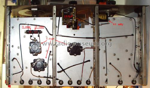
- Tensioni di funzionamento
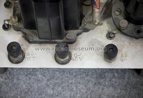
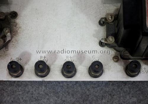
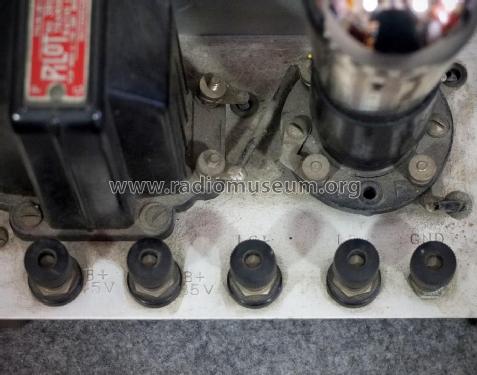
- Batterie (di accumulatori e/o a secco) / -4.5; 6; 22,5; 45; 45; 45; x Volt
- Altoparlante
- - Per cuffie o amplificatori esterni
- Materiali
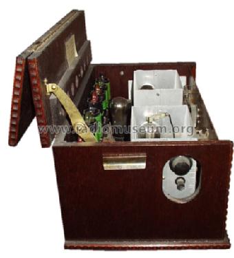
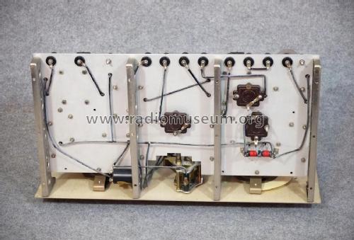
- Mobile di metallo
- Radiomuseum.org
- Modello: Super Wasp K-110 - Pilot Electric Mfg. Co. Radio
- Forma
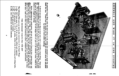
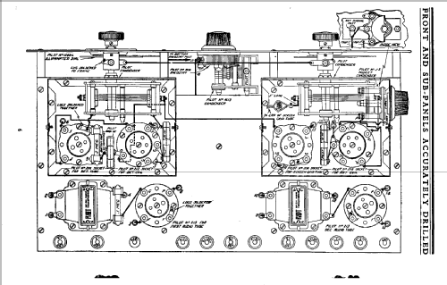
- Chassis o in scatola da montaggio
- Dimensioni (LxAxP)
- 18 x 7.5 x 9.5 inch / 457 x 191 x 241 mm
- Annotazioni
- Catalog is asking for identical Pilot tubes (sales promotion).
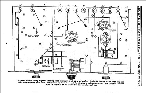
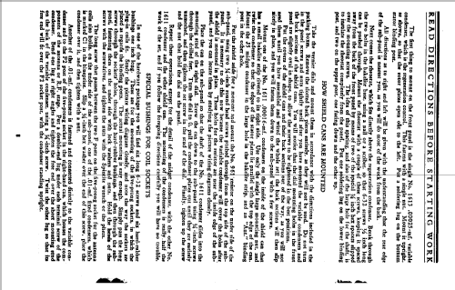
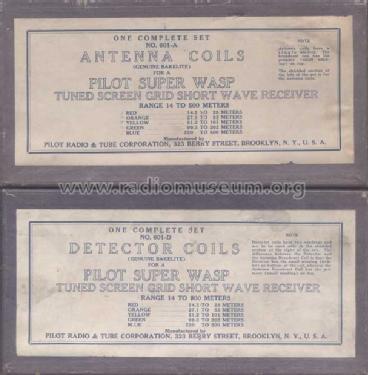
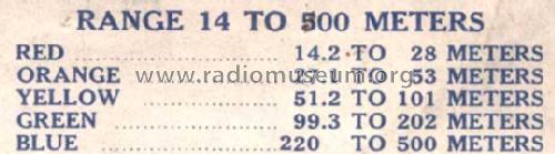
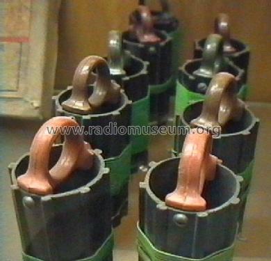
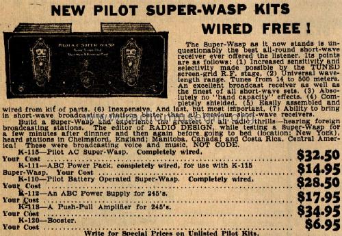
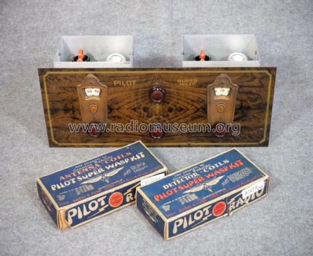
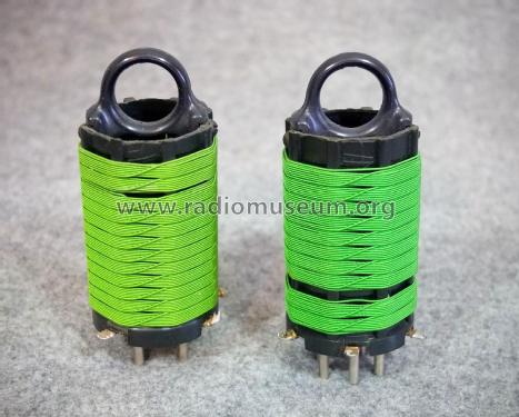
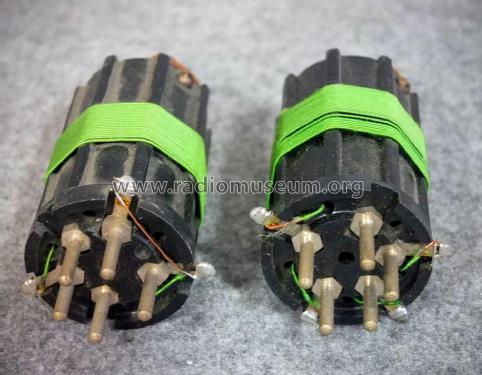
5 pairs of interchangeable coils for band selection. Catalog and assembly description of wave ranges (14.5-27 m; 26-50 m; 50-100 m; 100-200 m; 200-500 m) are not in accordance with reality, see photos.
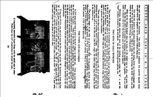
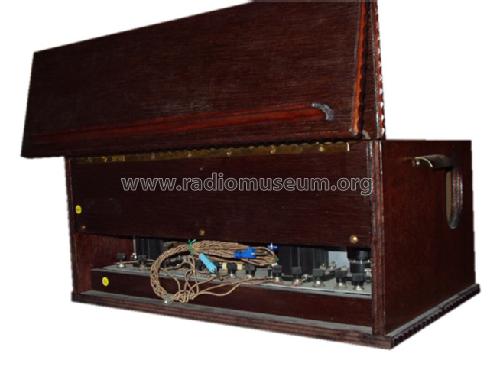
This was sold as a kit only. The cabinet in the photo was later custom built (1985).
The set can also be modified to use '99 tubes plus the '22. That requires an additional resistor and a separate power switch.
The date 1927 comes from a Pilot ad.
- Prezzo nel primo anno
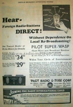
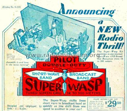
- 29.00 $
- Fonte esterna dei dati
- Ernst Erb
- Fonte dei dati
- Radio Collector`s Guide 1921-1932
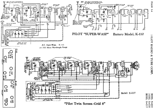
- Riferimenti schemi
- Rider's Perpetual, Volume 1 = 1931/1934 (for 1919-1931)
- Bibliografia
- Radio Manufacturers of the 1920's, Vol. 2 (Radio News June 1929)
- Letteratura / Schemi (1)
- Collector's Guide to Antique Radios (6th edition) (and: A Flick of the Switch)
- Altri modelli
-
In questo link sono elencati 544 modelli, di cui 273 con immagini e 412 con schemi.
Elenco delle radio e altri apparecchi della Pilot Electric Mfg. Co. (Radio Corp.); Brooklyn (NY)
Collezioni
Il modello Super Wasp fa parte delle collezioni dei seguenti membri.
Musei
Il modello Super Wasp può essere visto nei seguenti musei.
Discussioni nel forum su questo modello: Pilot Electric Mfg.: Super Wasp K-110
Argomenti: 1 | Articoli: 5
Hi Everyone,
I have recently acquired a Pilot Wasp Radio and I cannot seem to identify which model it is exactly. I think it may be a combination of several models.
It operates from 240V AC and has a filter power supply using an 80 rectifier.
The Valve lineup is 39 36 76 41 80.
It also came with a box of plugin coils.
The pictures of the radio are attached.
Allegati
- Pilot Wasp Front (50 KB)
- Pilot Wasp Top (64 KB)
- Pilot Wasp Bottom (72 KB)
- Pilot Wasp Coil Box (64 KB)
- Pilot Wasp Plugin Coils (62 KB)
- Pilot Wasp Document Cover (88 KB)
Gary Cowans, 13.May.14