X-65 no suffix
Pilot Electric Mfg. Co. (Radio Corp.); Brooklyn (NY)
- Produttore / Marca
- Pilot Electric Mfg. Co. (Radio Corp.); Brooklyn (NY)
- Anno
- 1935 ??
- Categoria
- Radio (o sintonizzatore del dopoguerra WW2)
- Radiomuseum.org ID
- 52096
-
- alternative name: Pilot Radio & Television || Pilot Radio and Tube || Pilot Radio Corporation

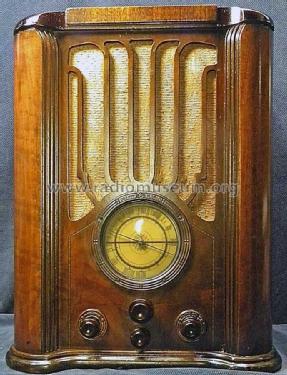
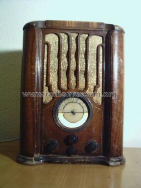

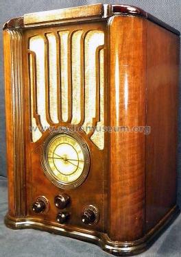

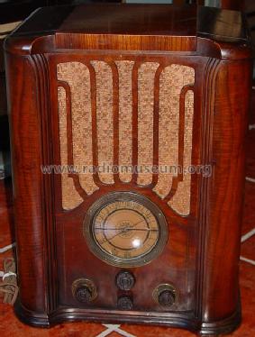
Front view.
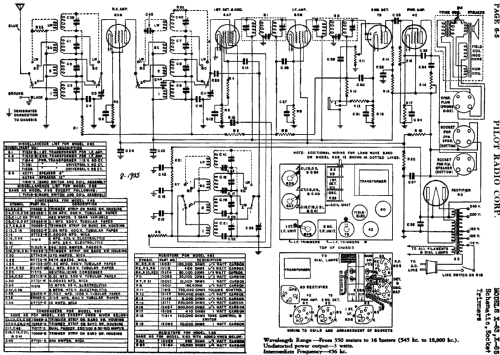
Clicca sulla miniatura dello schema per richiederlo come documento gratuito.
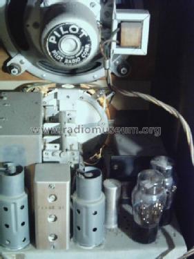
- Numero di tubi
- 6
- Principio generale
- Supereterodina (in generale); ZF/IF 456 kHz
- N. di circuiti accordati
- 9 Circuiti Mod. Amp. (AM)
- Gamme d'onda
- Onde medie (OM), lunghe (OL) e 2 onde corte (2 x OC).
- Tensioni di funzionamento
- Alimentazione a corrente alternata (CA) / 110; 125; 150; 220; 240 Volt
- Altoparlante
- AP elettrodinamico (bobina mobile e bobina di eccitazione/di campo)
- Potenza d'uscita
- 3 W (qualità ignota)
- Materiali
- Mobile in legno
- Radiomuseum.org
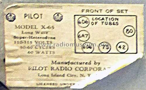
- Modello: X-65 [no suffix] - Pilot Electric Mfg. Co. Radio
- Forma
- Soprammobile verticale (sviluppato in altezza; no cattedrale, sin decorazioni).
- Annotazioni
- There are the models X-65-B and X-65-F known. Only Rider's lists this X-65 (without suffix), perhaps referring to the basic model or even the chassis (?).
- Fonte esterna dei dati
- Ernst Erb
- Riferimenti schemi
- Rider's Perpetual, Volume 6 = 1935 and before
- Altri modelli
-
In questo link sono elencati 544 modelli, di cui 271 con immagini e 410 con schemi.
Elenco delle radio e altri apparecchi della Pilot Electric Mfg. Co. (Radio Corp.); Brooklyn (NY)