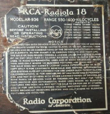
Radiola 18 AC AR-936
RCA (RCA Victor Co. Inc.); New York (NY)
- Produttore / Marca
- RCA (RCA Victor Co. Inc.); New York (NY)
- Anno
- 1928
- Categoria
- Radio (o sintonizzatore del dopoguerra WW2)
- Radiomuseum.org ID
- 54637
-
- alternative name: RCA Manufacturing || Victor Talking Machine
Beitman


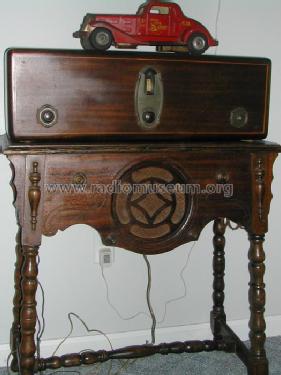
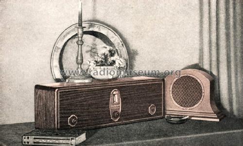
Vista frente perfil
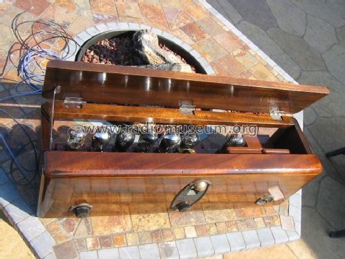
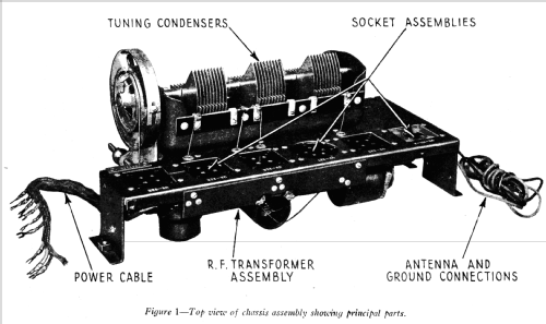
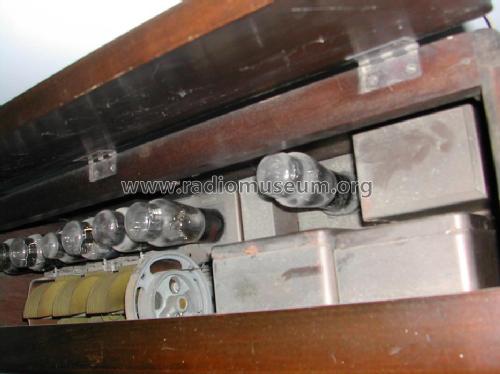
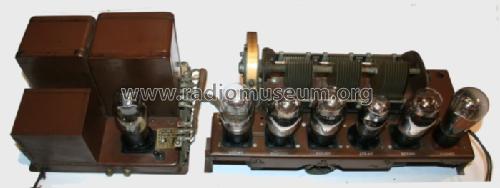
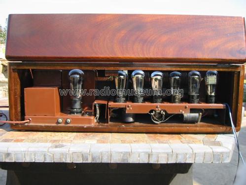
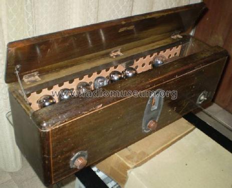
RCA Radiola 18 top view

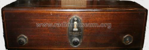
RCA Radiola 18 tuner chassis
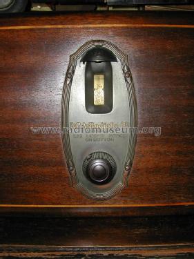


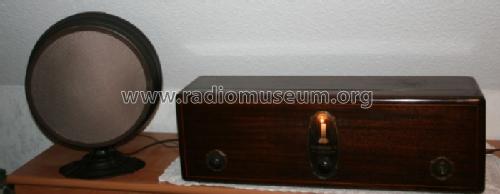
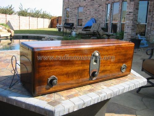
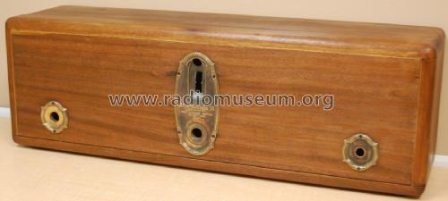
RCA Radiola 18 front view
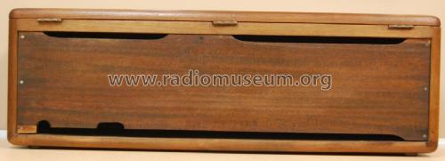
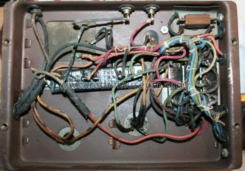
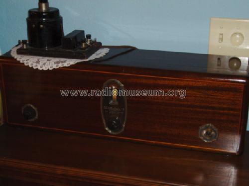
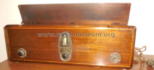
RCA Radiola 18 rear view
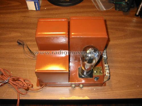
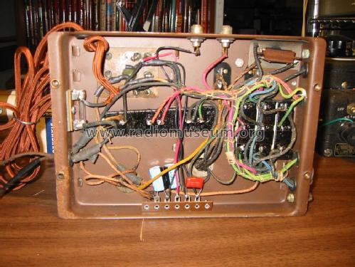
RCA Radiola 18 power supply chassis
USA_RCA_RADIOLA_18

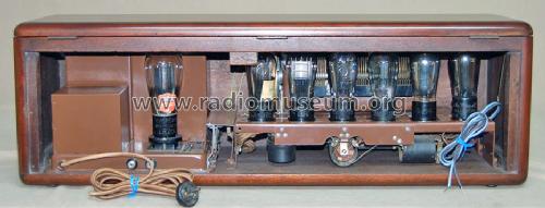
Vista de Back
Clicca sulla miniatura dello schema per richiederlo come documento gratuito.
- Numero di tubi
- 7
- Principio generale
- A circuiti accordati (amplif. diretta) senza reazione
- N. di circuiti accordati
- 3 Circuiti Mod. Amp. (AM)
- Gamme d'onda
- Solo onde medie (OM).
- Tensioni di funzionamento
- Alimentazione a corrente alternata (CA) / 110-120 Volt
- Altoparlante
- - Per cuffie o amplificatori esterni
- Materiali
- Mobile in legno
- Radiomuseum.org
- Modello: Radiola 18 AC AR-936 - RCA RCA Victor Co. Inc.; New
- Forma
- Soprammobile a cassapanca o cassetta, solitamente con coperchio (NON a leggio)
- Dimensioni (LxAxP)
- 27.5 x 9 x 7.5 inch / 699 x 229 x 191 mm
- Annotazioni
-
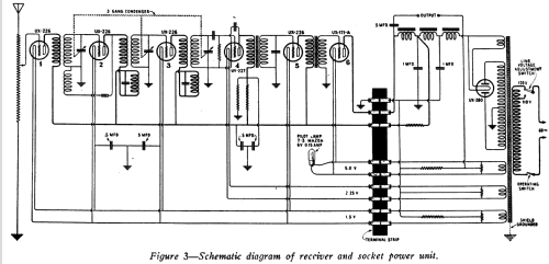
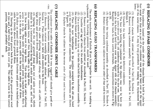
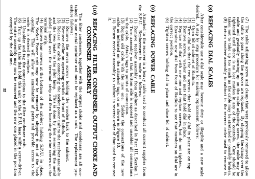
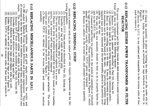
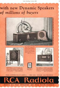
The RCA Radiola model 18 was introduced in the May 1928 issue of Radio Retailing at a price of $95 without tubes. Price with tubes was $122.50. The separate matching Radiola 100A speaker was an additional $29. The broadcast band coverage upper limit was 1400 kHz. The power unit chassis could be switched to either 110 VAC or 120 VAC.
- Peso netto
- 17.1 kg / 37 lb 10.6 oz (37.665 lb)
- Prezzo nel primo anno
- 95.00 USD
- Fonte esterna dei dati
- Ernst Erb
- Fonte dei dati
- The Radio Collector's Directory and Price Guide 1921 - 1965
- Riferimenti schemi
- Rider's Perpetual, Volume 1 = 1931/1934 (for 1919-1931)
- Bibliografia
- Collector's Guide to Antique Radios 4. Edition
- Letteratura / Schemi (1)
- "The Socket Power Transition, RCA Radiola 18" in The Spectrum Monitor 1-2024 by R Post
- Altri modelli
-
In questo link sono elencati 5143 modelli, di cui 3250 con immagini e 4180 con schemi.
Elenco delle radio e altri apparecchi della RCA (RCA Victor Co. Inc.); New York (NY)
Collezioni
Il modello Radiola 18 AC fa parte delle collezioni dei seguenti membri.
Musei
Il modello Radiola 18 AC può essere visto nei seguenti musei.
Discussioni nel forum su questo modello: RCA RCA Victor Co.: Radiola 18 AC AR-936
Argomenti: 2 | Articoli: 4
A common problem with Radiola 18 radio's is the tuning capacitor becomes frozen and will not turn. In many of these cases, the rotor and stator plates actually short together. Guest Bill Jeffrey came up with a good solution to this problem, which I found documented on the Nostalgiaair.org website. I have used this procedure to successfully repair this problem on both Radiola 18 and Radiola 16 radio's. (Both radio's use the same tuner design).
Bill Jeffrey has graciously given me permission to document his procedure here on Radio Museum. Thank you Bill!
Overhauling the RADIOLA 18 Tuning Condenser - By Bill Jeffrey 6/23/97
I smiled to myself as I dragged the dusty Radiola 18 out from a dark corner of the antique shop in the tourist town of Ogunquit, Maine. I hid my smile as I talked the price down - way down. It was off-season, after all. But my smile faded considerably when I got it home and discovered that the tuning condenser was frozen solid. Although no damage was apparent under the grunge, it would not turn even slightly, and I recalled the hint of a smile on the shop owner's face as I had paid her. Since I was only a novice, it was just possible that I had gotten in over my head. But the rest of the radio looked good, and it was fully tubed, so I set out to overhaul the balky condenser.
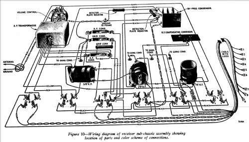
Like many things of its era, the Radiola 18 tuning condenser is constructed of leftover battleship parts - nothing subtle here. Because of this, the overhaul turned out to be reasonably straightforward. The first step was to remove the radio's chassis from the wooden case, remove the tubes, and vacuum out as much dirt and dust as possible. This revealed the condenser assembly shown in the drawing.
The next step is to remove the condenser from the chassis. Unsolder the four wires (ground plus the three condenser connections) which come up through grommets in the top of the chassis. Then remove the three bolts which hold the unit to the chassis. The unit lifts off, with the shaft for the tuning knob and the dial cord (not shown in the drawing) still attached. In my unit, the "dial cord" is actually braided phosphor-bronze wire, with metal eyelets crimped into each end. Apparently easy tuning had yet to be invented in 1924.
Remove the dial cord, making a careful sketch of the arrangement as you do so. Once removed, the re-stringing sequence is not obvious.

As the figure shows, the tuning condenser consists of three identical sections mounted on a common shaft. The shaft passes through holes drilled in the ends of a sheet steel bathtub, about 8.5" long X 3" wide X 2" deep. One end of the shaft (the left end in the drawing) rides free. The other end is the "business end". The tuning dial is mounted on the end of the shaft, held in place with a pin which passes through the shaft and the outer hub of the pulley. Inside the bathtub, a brass bushing secures the shaft, held in place with a similar pin. A phosphor/bronze wave washer between this inner bushing and the frame keeps the shaft from sliding back and forth.
After some examination, it became apparent that the rotor was frozen because the hub of the tuning dial pulley rides directly on the steel of the frame. Over the years, the metal had worn and galled, forming a rough surface. This was aggravated by the fact that the wave washer applied enough force to hold bulldozer treads together - like I said, nothing subtle here. At some time in the past, the rough area had been greased, which only attracted grit and made the problem worse. It was clear that the pulley would have to come off.
Drive out the outer lock pin. I used a small nail, the same diameter as the pin, as a punch, but be sure to grind off the point and leave a flat end before using it. Note that one end of the lock pin is bigger than the other - drive from the small end, and be gentle. A series of light taps should be sufficient to back out the pin. If it is stubborn, use a fine file to remove the peened-over head at one end of the pin, and try again.
Once the outer pin is out and safely retrieved, remove the tuning dial. Do this carefully - the dial is actually a flexible brass band wrapped around a cast pot metal framework, and the framework may have numerous splits and cracks. If it breaks when you remove it, your project will most likely be over. Pot metal is virtually irrepairable.
Remove the inner lock pin and save it. Slide the inner bushing to the left, and remove the shaft from the bathtub. Clean all the parts, including the bathtub, in a solvent which will remove hardened grease and varnish. Use a soft paintbrush to work the solvent down between the rotor plates without bending them, and then repeat for the stator plates. If your unit is really dirty, each of the three stator sections can be removed from the bathtub and washed separately.
After I cleaned and reassembled the unit, the worn area still prevented the shaft from turning smoothly. It was apparent that a thin Teflon washer was needed, between the worn surfaces of the bathtub and the tuning dial pulley. Although I had several washers in the wrong size, I could not locate one which fit. The local home center had nylon washers, but they were quite thick - much too thick to fit in the space available. In the end, a very good solution turned out to be a washer which I cut freehand from a gallon plastic milk jug - the spirit of improvisation still lives! Though it was much thinner than the nylon, the force exerted by the wave washer didn't permit even this thickness, so I used a flat file to remove about 1/32" from the worn bearing surface of the tuning dial's inner hub. The result was a condenser which turns as smooth as silk.
Reassemble the condenser, setting the pins lightly but firmly. Before remounting it in the chassis, turn the shaft so that the rotor and stator plates are fully meshed. Examine them closely, and be sure that all the rotor plates are centered between the stator plates. If they are not centered, loosen the four screws which hold each set of stators, and tweak the stator set into place.
Finally, restring the dial cord according to your careful sketch, and remount the unit on the chassis. Before resoldering the wire connections, check the grommets where the wire comes up through the top of the chassis, and replace if necessary. That's it!
John Kusching, 19.Nov.14
Hi:
I just acquired a Radiola 18... I have a grasp of how it works but have never seen a speaker like the one that came with it. It appears to have a permanent magnet ("U" shaped), and has some kind of transformer (I believe) mounted on the frame and has what I believe is an actuator coil for the cone. Can anyone tell me what the components actually are and how to test them? The cone is completely destroyed but I hope to make one if the electrical components are OK.
Thanks- Tom
Thomas Ranz, 28.Jul.12