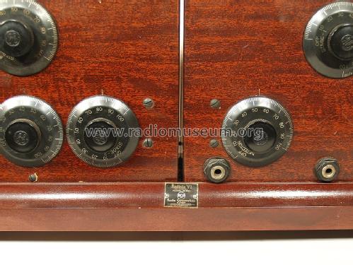
Radiola VI (6) AR-895
RCA (RCA Victor Co. Inc.); New York (NY)
- Pays
- Etats-Unis
- Fabricant / Marque
- RCA (RCA Victor Co. Inc.); New York (NY)
- Année
- 1923
- Catégorie
- Radio - ou tuner d'après la guerre 1939-45
- Radiomuseum.org ID
- 54632
-
- alternative name: RCA Manufacturing || Victor Talking Machine


Aus RCA-Manual

Ebay Item Number: 190794799565
Ebay Item Number: 190794799565

Ebay Item Number: 190794799565
Ebay Item Number: 190794799565
Ebay Item Number: 190794799565
Ebay Item Number: 190794799565
Ebay Item Number: 190794799565
Ebay Item Number: 190794799565

Ebay Item Number: 190794799565

Ebay Item Number: 190794799565
Cliquez sur la vignette du schéma pour le demander en tant que document gratuit.
- No. de tubes
- 6
- Principe général
- Récepteur TRF - par réaction (régénératif)
- Gammes d'ondes
- PO uniquement
- Tension / type courant
- Piles (rechargeables ou/et sèches)
- Haut-parleur
- - Pour casque ou amplificateur BF
- Matière
- Boitier métallique
- De Radiomuseum.org
- Modèle: Radiola VI AR-895 - RCA RCA Victor Co. Inc.; New
- Forme
- Modèle de table générique
- Dimensions (LHP)
- 23.5 x 11 x 7 inch / 597 x 279 x 178 mm
- Remarques
- The RAdiola VI (6) is also model AR-895. A dressed up AA1520 and AA1400, required the Wireless Specialty tuned loop AG1380. See the forum text below for detailled instructions etc. for the Radiola VI model AR-895 of RCA. You can use either 6 tubes UV201A, also called 01A or the UV200 as detector tube and 5 UV201, later called .01 or UV201A.
- Prix de mise sur le marché
- 162.00 $
- Source extérieure
- Ernst Erb
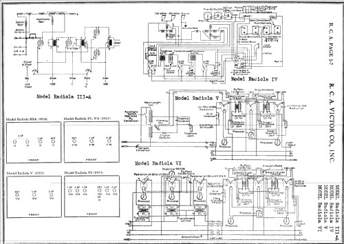
- Source du schéma
- Rider's Perpetual, Volume 1 = 1931/1934 (for 1919-1931)
- Littérature
- Collector's Guide to Antique Radios 4. Edition
- Schémathèque (1)
- Radio Manufacturers of the 1920's, Vol. 3
- D'autres Modèles
-
Vous pourrez trouver sous ce lien 5179 modèles d'appareils, 3252 avec des images et 4216 avec des schémas.
Tous les appareils de RCA (RCA Victor Co. Inc.); New York (NY)
Collections
Le modèle Radiola fait partie des collections des membres suivants.
Contributions du forum pour ce modèle: RCA RCA Victor Co.: Radiola VI AR-895
Discussions: 1 | Publications: 2
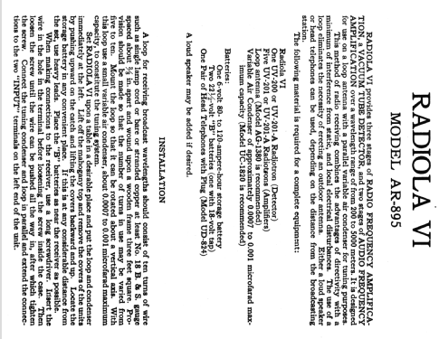
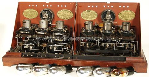
Thanks to Ramon Gancedo, Madrid, Spain who decided to scan some pages of the RCA-Manual for www.radiomuseum.org and Thomas Günzel, Ulm, Germany who did the OCR-Recognition I am able to present you an article which shows the function, the build up and the operation of a Regenerative Receiver and Amplifier. We now worked the same way for model Radiola VI (six) Model AR895.
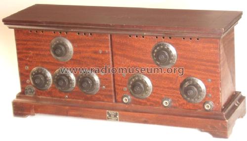
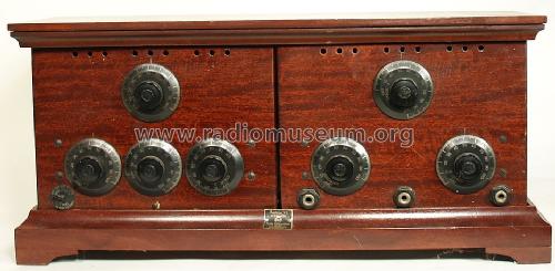
Radiola VI, model AR-895 is designed for use on a loop antenna with a parallel variable air condenser for tuning purposes. This method of radio receiving combines the advantages of directivity with a minimum of interference from static, and local electrical disturbances. The use of a loop eliminates the necessity of erecting an outdoor antenna. Either a loud speaker or head telephones can be used, depending on the distance from the broadcasting station.
INSTALLATION
When making connections to the receiver, use a long screwdriver. Insert the wire in the hole in the terminal before loosening the screw inside the case. Then loosen the screw until the wire can be pushed all the way in, after which tighten the screw. Connect the tuning condenser and loop in parallel and extend the connections to the two "INPUT" terminals on the left end of the unit.
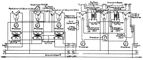
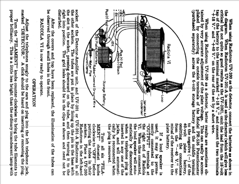
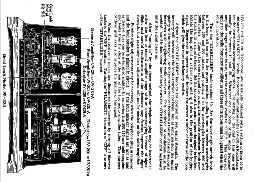
When using Radiotron UV-200 as the detector, connect the batteries as shown in the diagram. When Radiotron UV-201-A is used as the detector (which will give less critical but not quite so good results as the UV-200), omit the lead from the 18-volt tap of the battery to the terminal marked "+18 V." and connect the two terminals "+18 V." and "+40 V." on the rear of the set by a short wire.
When using Radiotron UV-200 as a detector, better results are sometimes obtained by very accurate adjustment of the plate voltage. This can easily be accomplished by connecting the outside terminals of the Model PR-536 Potentiometer (purchased separately) across the 6-volt storage battery and the middle terminalto the negative (—) of the 40-volt plate battery, omitting the connections from the "-40 V." terminal of the receiver to the plate battery.

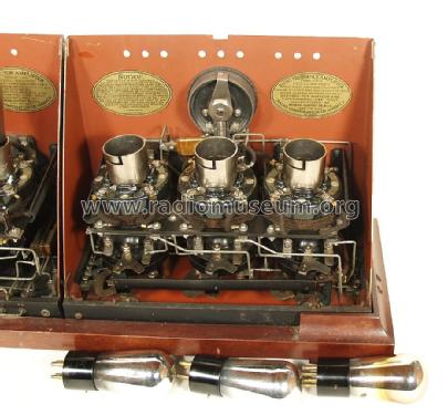
Turn all six "FILAMENT" rheostat knobs clockwise to "OFF"' before putting the tubes in their sockets. Place a UV-200 Radiotron in the left-hand socket of the Detector-Amplifier unit, and UV-201 or UV-201-A Radiotrons in all the other sockets. The tubes are put in place by lining up the pin in the base with the slot in the socket, pressing downward on the tube, and then turning it to the right into position. The grid leaks should be in the clips as shown and need not be disturbed.
After the covers and top have been replaced, the illumination of the tubes can be observed through small holes in the front.
RADIOLA VI is now ready to operate.
OPERATION
For proper illumination of the UV-201-A Radiotrons, see the instructions accompanying tubes. The setting of the dial in this case will usually be between 10 and 50. Whenever one or both of the audio frequency amplifier stages are not in use, turn the respective knobs to "OFF." This does not apply to the radio frequency amplifier, as all three of its tubes must be lighted when the set is in operation.
Tune to the desired signal by turning the variable condenser knob over the scale until a signal is heard. Set the knob at the point where the signal is loudest. Rotate the loop about a vertical axis, setting it also in the position of the loudest signal. Experience in operation will indicate the correct number of turns of the loop which will give the most satisfactory results.

operation).


March 24th 2007: Pictures added.
Ernst Erb, 23.Mar.07