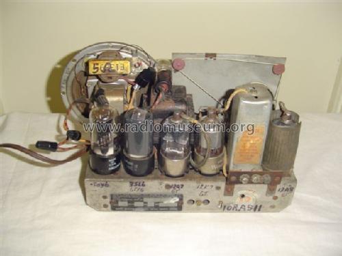
Rogers 15/51 Ch= 10RA511
Rogers-Majestic, Standard Radio Manufacturing, Rogers Radio Tubes; Toronto
- País
- Canada
- Fabricante / Marca
- Rogers-Majestic, Standard Radio Manufacturing, Rogers Radio Tubes; Toronto
- Año
- 1940/1941
- Categoría
- Radio - o Sintonizador pasado WW2
- Radiomuseum.org ID
- 111256
-
- alternative name: Rogers Radio Tube


Haga clic en la miniatura esquemática para solicitarlo como documento gratuito.
- Numero de valvulas
- 5
- Principio principal
- Superheterodino en general; ZF/IF 456 kHz
- Número de circuitos sintonía
- 6 Circuíto(s) AM
- Gama de ondas
- OM (onda media) solamente
- Tensión de funcionamiento
- Red: Corriente alterna (CA, Inglés = AC) / 117 Volt
- Altavoz
- Altavoz electrodinámico (bobina de campo)
- Material
- Madera
- de Radiomuseum.org
- Modelo: Rogers 15/51 Ch= 10RA511 - Rogers-Majestic, Standard
- Forma
- Sobremesa apaisado (tamaño grande).
- Anotaciones
- Rogers 15/52AL, 15/52L, 15/52X, Majestic 4151, 4152X, 4152AL, 4152L, De Forest 15/41, X25/41, AL25/41 and L24/41 are all electronically identical to this model.
- Referencia esquema
- Radio College of Canada
- Mencionado en
- RCC Rogers-Majestic section page 77 & 78
- Autor
- Modelo creado por Job Goudie. Ver en "Modificar Ficha" los participantes posteriores.
- Otros modelos
-
Donde encontrará 555 modelos, 235 con imágenes y 506 con esquemas.
Ir al listado general de Rogers-Majestic, Standard Radio Manufacturing, Rogers Radio Tubes; Toronto
Colecciones
El modelo Rogers 15/51 es parte de las colecciones de los siguientes miembros.
Contribuciones en el Foro acerca de este modelo: Rogers-Majestic,: Rogers 15/51 Ch= 10RA511
Hilos: 1 | Mensajes: 8
I still haven't solved the trouble with this Rogers Majestic 15/51 The DC voltages seem to be all low especially for the 12Q7 tube...32v..However, I do get a loud hum when placing my finger on the grid cap of this tube and when placing a screwdriver on the gridcap, with my finger on the screwdriver I pick up a station although very weak......Any ideas as to what may be wrong with this radio?? I have replaced just about all of the capacitors including a resistor which ran from pin 5 of 35L6 to pin 3 of 12Q7.
Thanks
Job
Job Goudie, 14.Jan.07