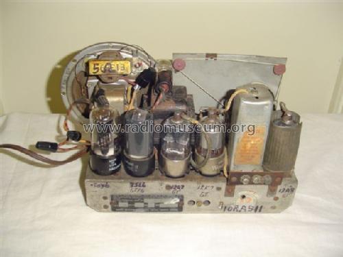
Rogers 15/51 Ch= 10RA511
Rogers-Majestic, Standard Radio Manufacturing, Rogers Radio Tubes; Toronto
- Pays
- Canada
- Fabricant / Marque
- Rogers-Majestic, Standard Radio Manufacturing, Rogers Radio Tubes; Toronto
- Année
- 1940/1941
- Catégorie
- Radio - ou tuner d'après la guerre 1939-45
- Radiomuseum.org ID
- 111256
-
- alternative name: Rogers Radio Tube


Cliquez sur la vignette du schéma pour le demander en tant que document gratuit.
- No. de tubes
- 5
- Principe général
- Super hétérodyne (en général); FI/IF 456 kHz
- Circuits accordés
- 6 Circuits MA (AM)
- Gammes d'ondes
- PO uniquement
- Tension / type courant
- Alimentation Courant Alternatif (CA) / 117 Volt
- Haut-parleur
- HP dynamique à électro-aimant (électrodynamique)
- Matière
- Boitier en bois
- De Radiomuseum.org
- Modèle: Rogers 15/51 Ch= 10RA511 - Rogers-Majestic, Standard
- Forme
- Modèle de table profil bas (grand modèle).
- Remarques
- Rogers 15/52AL, 15/52L, 15/52X, Majestic 4151, 4152X, 4152AL, 4152L, De Forest 15/41, X25/41, AL25/41 and L24/41 are all electronically identical to this model.
- Source du schéma
- Radio College of Canada
- Littérature
- RCC Rogers-Majestic section page 77 & 78
- Auteur
- Modèle crée par Job Goudie. Voir les propositions de modification pour les contributeurs supplémentaires.
- D'autres Modèles
-
Vous pourrez trouver sous ce lien 555 modèles d'appareils, 235 avec des images et 506 avec des schémas.
Tous les appareils de Rogers-Majestic, Standard Radio Manufacturing, Rogers Radio Tubes; Toronto
Collections
Le modèle Rogers 15/51 fait partie des collections des membres suivants.
Contributions du forum pour ce modèle: Rogers-Majestic,: Rogers 15/51 Ch= 10RA511
Discussions: 1 | Publications: 8
I still haven't solved the trouble with this Rogers Majestic 15/51 The DC voltages seem to be all low especially for the 12Q7 tube...32v..However, I do get a loud hum when placing my finger on the grid cap of this tube and when placing a screwdriver on the gridcap, with my finger on the screwdriver I pick up a station although very weak......Any ideas as to what may be wrong with this radio?? I have replaced just about all of the capacitors including a resistor which ran from pin 5 of 35L6 to pin 3 of 12Q7.
Thanks
Job
Job Goudie, 14.Jan.07