Autodyne 38
SBR Société Belge Radio-Electrique, Bruxelles
- Country
- Belgium
- Manufacturer / Brand
- SBR Société Belge Radio-Electrique, Bruxelles
- Year
- 1922 ?
- Category
- Broadcast Receiver - or past WW2 Tuner
- Radiomuseum.org ID
- 229050
- Number of Tubes
- 4
- Main principle
- TRF with regeneration; something special ? Please give information (notes)
- Wave bands
- Wave Bands given in the notes.
- Power type and voltage
- Storage and/or dry batteries / 4 & 80 Volt
- Loudspeaker
- - For headphones or amp.
- Material
- Wooden case
- from Radiomuseum.org
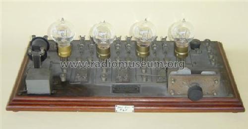
- Model: Autodyne 38 - SBR Société Belge Radio-
- Shape
- Tablemodel, low profile (big size).
- Notes
-
- Amateur receiving equipment based on the Brillouin principle (Autodyne).
- It could work with frequencies in the range from 30kHz (10000m) up to 375kHz (800m).
- A loop antenna and a tuning capacitor must be connected to the input of the unit to allow tuning to a radio station.
- This radio could be used to receive public radio stations with modulated carrier by using it as a regenerative radio unit by regulating the "Compensateur"1 just before the onset of the local oscillation. The radio has its maximum sensitivity at that point. The detection was done by the last tube.
- This radio could also be used to receive telegraphic transmissions (Morse code) by continuous wave. Here, one had to turn the "Compensateur"1 to the point that local oscillation started at a frequency close to the frequency of the desired radio station, resulting in an audible tone, being the offset frequency between the carrier and local oscillation, in the rhythm of the Morse code.
- This radio could also be used to receive telegraphic transmissions (Morse code) by damped wave, generated by a spark gap transmitter. The Morse code became audible at the point just before the onset of the local oscillation, without passing that point. The sound had a throbbing (beating) characteristic.
- Another use for this radio was to receive military communications and time signals. In that era, the Eiffel tower in Paris (near 150 kHz) send twice daily a signal to permit clock synchronisation based on the reference clocks of the Paris observatory operated by the French Bureau of Longitude.
- See also the article from Léon Brillouin: " Les amplificateurs à résistances" at the bottom of the BR4 page.
- See also S.I.F. models BR4, BR4bis, BR8.
1Compensateur: the differential variable capacitor to control the positive and negative feedback (see schematic). Not a butterfly capacitor.
- Sources:
- "Pratique et théorie de la T.S.F.", 2ième édition, page 428 et 429, par Paul Berché, Paris 1930.
- "Time signal stations" by Michael A. Lombardi.
- Author
- Model page created by Dirk Bladt. See "Data change" for further contributors.
- Other Models
-
Here you find 735 models, 682 with images and 418 with schematics for wireless sets etc. In French: TSF for Télégraphie sans fil.
All listed radios etc. from SBR Société Belge Radio-Electrique, Bruxelles