Alpha-Standard W alt (RE134)
Schaub und Schaub-Lorenz
- Pays
- Allemagne
- Fabricant / Marque
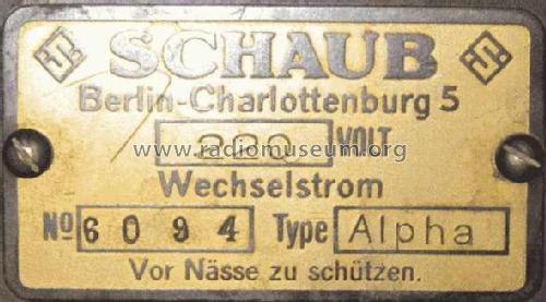
- Schaub und Schaub-Lorenz
- Année
- 1930–1932
- Catégorie
- Radio - ou tuner d'après la guerre 1939-45
- Radiomuseum.org ID
- 6241


Cliquez sur la vignette du schéma pour le demander en tant que document gratuit.
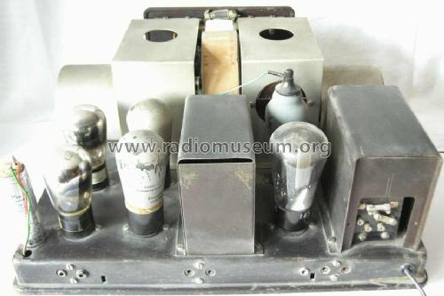
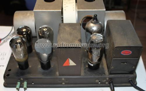
- No. de tubes
- 6
- Principe général
- Récepteur TRF - par réaction (régénératif); 1 Spécial; 2 Etage(s) BF; Détection par courbure d'anode.
- Circuits accordés
- 2 Circuits MA (AM)
- Gammes d'ondes
- PO et GO
- Tension / type courant
- Alimentation Courant Alternatif (CA) / 110-220 Volt
- Haut-parleur
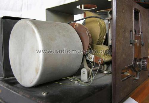
- - Ce modèle nécessite des HP externes
- Matière
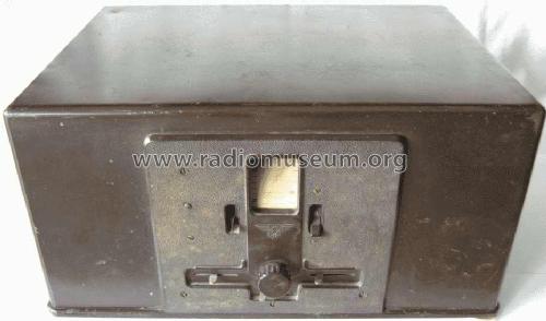
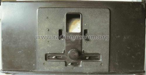
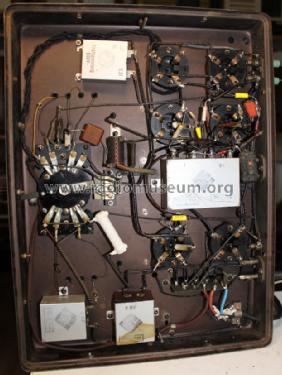
- Boitier métallique
- De Radiomuseum.org
- Modèle: Alpha-Standard W [alt ] - Schaub und Schaub-Lorenz
- Forme
- Modèle de table profil bas (grand modèle).
- Dimensions (LHP)
- 395 x 180 x 295 mm / 15.6 x 7.1 x 11.6 inch
- Remarques
-
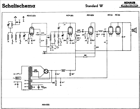
Im Schaltbild gezeigte REN904 ist der spätere Universalersatz für die Originalbestückung REN804 und REN1004.
Auch mit nur einer Endröhre RE134
Preis ohne Röhren, zusätzlich Röhresatz:
- RENS1204, REN1004, REN804, RE134, Philips 1801 Preis: 67,- RM
- RENS1204, REN1004, REN804, 2 x RE134, Philips 1801 Preis: 77,50 RM
- Prix de mise sur le marché
- 165.00 RM !
- Source
- Katalog Radio-Zentrale Prohaska 1930/31 (dick) / Radiokatalog Band 1, Ernst Erb
- Source du schéma
- Röhren in FS-Bestückungstabellen
- Littérature
- Kat.Radio Arlt 1931
- Schémathèque (1)
- Katalog Radio-Zentrale Prohaska 1931/32
- D'autres Modèles
-
Vous pourrez trouver sous ce lien 974 modèles d'appareils, 833 avec des images et 691 avec des schémas.
Tous les appareils de Schaub und Schaub-Lorenz
Collections
Le modèle Alpha-Standard fait partie des collections des membres suivants.
Contributions du forum pour ce modèle: Schaub und Schaub-: Alpha-Standard W
Discussions: 2 | Publications: 5
Can anyone explain how this radio does the AM detection ? Grid of REN804 ?
thanks for your attention,
Dirk Bladt
Dirk Bladt, 24.Mar.11
Die Alpha Geräte haben ein "elegantes Schleiflackgehäuse", während die Beta Geräte ein "luxeriöses Edelholzgehäuse" haben, wie im Prohaska Katalog von 1930/31 nachzulesen ist (Nr. 3126 & 3127).
Bei beiden Gehäuseformen gibt es für das Chassis die Varianten "Standard" und "Kraft", die sich in der Endstufe und für Wechselstrom auch im Gleichrichter unterscheiden.
Für beide Chassisarten gibt es eine Wechselstrom- und eine Gleichstromvariante.
In den Serviceunterlagen der Fa. Schaub wird daher in den Schaltbildern nur zwischen "Standard" und "Kraft" und "G" und "W" unterschieden.
Hier zunächst "Kraft G"
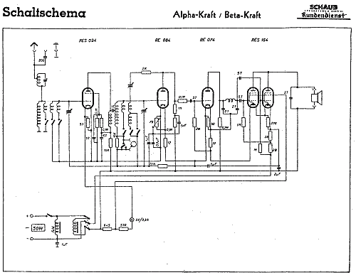
Für "Standard G" ist kein Schaltbild angegeben. (Vermutlich wurde nur die RES164s durch die RE134s ersetzt.)
Für "Standard W" und "Kraft W" gibt es Schaltbilder.
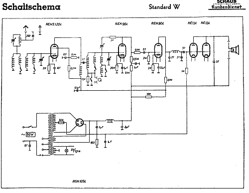
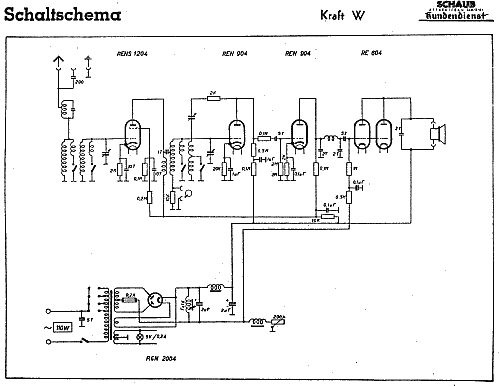 Bei den "W" Typen besteht ja zusätzlich ein Unterschied im Netzteil.
Da die Empfänger ursprünglich nur den alten Frequenzbereich der Mittelwelle umfaßten, gab es von Schaub auch noch eine Anweisung, wie auf den Bereich 510 KHz bis 1620 KHz umzustellen sei:
Frage an die Modell-Admins: Wo sollten die Schaltbilder hingeladen werden? Jeweils zu Alpha oder zu Beta oder zu beiden?
MfG DR
Bei beiden Gehäuseformen gibt es für das Chassis die Varianten "Standard" und "Kraft", die sich in der Endstufe und für Wechselstrom auch im Gleichrichter unterscheiden.
Für beide Chassisarten gibt es eine Wechselstrom- und eine Gleichstromvariante.
In den Serviceunterlagen der Fa. Schaub wird daher in den Schaltbildern nur zwischen "Standard" und "Kraft" und "G" und "W" unterschieden.
Hier zunächst "Kraft G"
Für "Standard W" und "Kraft W" gibt es Schaltbilder.
Da die Empfänger ursprünglich nur den alten Frequenzbereich der Mittelwelle umfaßten, gab es von Schaub auch noch eine Anweisung, wie auf den Bereich 510 KHz bis 1620 KHz umzustellen sei:
- Spule im Primärkreis L1 8 Windungen abwickeln
- Spule im Sekundärkreis L2 15 Windungen abwickeln
- parallel zu L2 ein Trimmer von ungefähr 10 pF legen. Dieser Trimmer wird gleichzeitig zur Eichung der Mittelwellenskala benützt.
Frage an die Modell-Admins: Wo sollten die Schaltbilder hingeladen werden? Jeweils zu Alpha oder zu Beta oder zu beiden?
MfG DR
Dietmar Rudolph † 6.1.22, 08.Jun.07