Marloffstein 1 (I)
Siemens (& Halske, -Schuckert Werke SSW, Electrogeräte); Berlin, München
- País
- Alemania
- Fabricante / Marca
- Siemens (& Halske, -Schuckert Werke SSW, Electrogeräte); Berlin, München
- Año
- 1946/1947
- Categoría
- Radio - o Sintonizador pasado WW2
- Radiomuseum.org ID
- 5297


Chassis Number 560 384


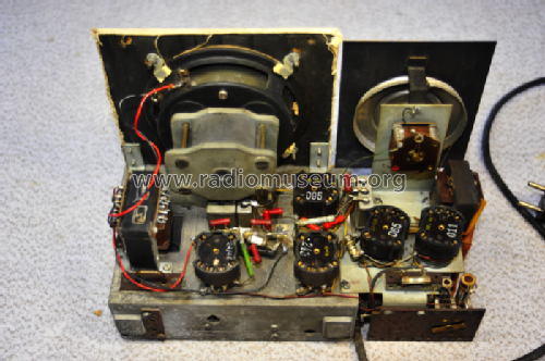
eigenes Gerät

eigenes Gerät

eigenes Gerät

eigenes Gerät

eigenes Gerät
Haga clic en la miniatura esquemática para solicitarlo como documento gratuito.
- Numero de valvulas
- 5
- Principio principal
- RFS con reacción (regenerativo); 2 Etapas de AF
- Número de circuitos sintonía
- 1 Circuíto(s) AM
- Gama de ondas
- OM y OL
- Tensión de funcionamiento
- Red: Aparato AC/DC. / DC: 110; 220 or AC: 110; 220 Volt
- Altavoz
- Altavoz dinámico (de imán permanente)
- Material
- Madera
- de Radiomuseum.org
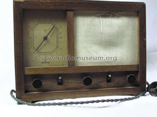
- Modelo: Marloffstein 1 - Siemens & Halske, -Schuckert
- Forma
- Sobremesa de tamaño mediano sin botonera <= 35 cm. (Incluso portables pero sólo con alimantación por red).
- Ancho, altura, profundidad
- 305 x 225 x 167 mm / 12 x 8.9 x 6.6 inch
- Anotaciones
-
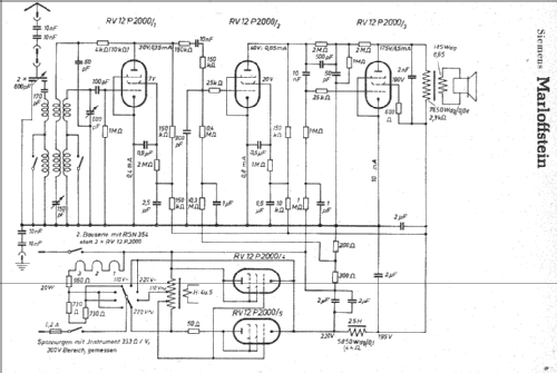
Der Siemens-Empfänger Marloffstein verwendet für Betrieb am Wechselstromnetz 110/220V einen Autotrafo mit separater Heizwicklung für 2x RV12P2000, die als Gleichrichter parallel geschaltet sind.
In Stellung Gleichstrom 110/220V sind diese Röhren Rö. 4 und 5 nicht in Funktion, die Netzspannung ist direkt zur Siebkette durchgeschaltet.
Lediglich das originale Hersteller-Schema zeigt die Spannungswerte für 3 Netzspannungen 220VAC, 220VDC und 110VDC.
Siehe auch technisch identisches Modell Marloffstein aus Fertigung Fernmeldewerk Arnstadt.
- Peso neto
- 4.1 kg / 9 lb 0.5 oz (9.031 lb)
- Procedencia de los datos
- Radiokatalog Band 1, Ernst Erb
- Referencia esquema
- Lange + Schenk Heft 29 von 1947
- Mencionado en
- Funkgeschichte der GFGF (9388)
- Documentación / Esquemas (1)
- -- Original-techn. papers.
- Otros modelos
-
Donde encontrará 2543 modelos, 2154 con imágenes y 1347 con esquemas.
Ir al listado general de Siemens (& Halske, -Schuckert Werke SSW, Electrogeräte); Berlin, München
Colecciones
El modelo Marloffstein es parte de las colecciones de los siguientes miembros.
Contribuciones en el Foro acerca de este modelo: Siemens & Halske, -: Marloffstein 1
Hilos: 2 | Mensajes: 14
The description and operation is described on page 4 of the Original brochure, and I include the German language text, and the translations from Babelfish and my edits (which are probably in error - as I have been told).
I have also detected a 1M ohm resistor leading into the plate circuit of the audio output tube. . . .the schematic depicts a 2M ohm, then another 2M ohm resistor leading into the tube.
Translations are as follow:
ORIGINAL
Dabei gilt die obere Hälfte der Skala (M). Beim Empfang nahe liegender starker Sender (Ortssender) wird der Drehknopf für die Rückkopplung (der mittlere) bis zum Anschlag nach links gedreht und die Lautstärke mit dem rechten Drehknopf geregelt. Hierauf wird mit dem Abstimmknopf die Einstellung nochmals verbessert.
Bei Farnempfang kann durch Drehen des Rückkopplungsknopfes nach rechts eine zusätzliche Erhöhung der Lautstärke und der Trennschärfe erreicht werden. Durch Betätigen des Lautstärkeknopfes wird der Empfang dann wieder aus normale Lautstärke eingeregelt und am Abstimmknopf die Einstellung verbessert. Die Rückkopplung darf nur bis kurz vor dem Einsetzen des Pfeiftones (Schwingungseinsatz)nach rechts gedreht werden.
BABELFISH
The following procedures apply to the upper half of the scale (M). With the receipt close lying strong transmitter (short-distance transmitters) is turned to the left the rotary button for the feedback (the middle) up to the notice and the volume with the right rotary button is regulated. With the co-ordination button the attitude is again improved on that.
With fern receipt through tricks of the feedback button an additional increase of the volume and the discrimination can be achieved to the right. The receipt is then in-regulated again from normal volume and improved pressing of the volume button at the co-ordination button the attitude. The feedback may only to short before using the whistler (Schwingungseinsatz)nach to be right turned.
SARBELL TRANSLATION
The following procedures apply for the upper half of the radio dial scale (M). With the reception of nearby strong transmitters (local stations), the rotary knob for the feedback (the middle) is turned to the left up to the stop, and the volume is regulated with the right rotary knob. With very slight adjustment of the feedback knob, the overall reception can be improved again slightly.
With weak reception, additional increase of the volume and station discrimination can be achieved through manual adjustments of the feedback knob slightly more to the right. The reception is then again fed back from the normal volume, and improved by rotating the volume knob while slight adjustment is made to the tuning and feedback knobs. The feedback knob may only be turned a short distance to the right (clockwise) before the "whistling sound" begins to occur as the knob is turned further to the right.
Respectfully,
robert Sarbell
Robert Sarbell † 22.3.22, 21.Sep.05
Also, the schematic does not depict a lamp for the illumination of the dial - I presume there was no requirement to illuminate the dial in a dimly lit room.
Respectfully,
RoSa
Robert Sarbell † 22.3.22, 31.Aug.05