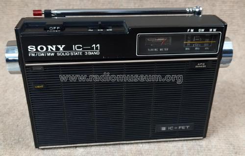
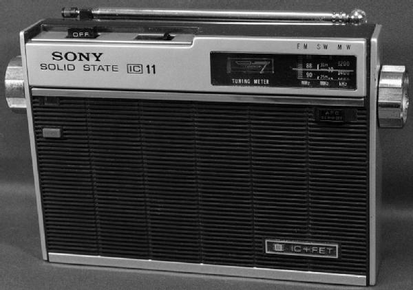
IC-11 3Band IC+FET ICF-110W
Sony Corporation; Tokyo
- País
- Japon
- Fabricante / Marca
- Sony Corporation; Tokyo
- Año
- 1970 ??
- Categoría
- Radio - o Sintonizador pasado WW2
- Radiomuseum.org ID
- 156930


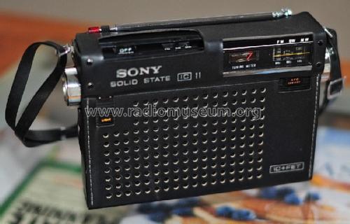
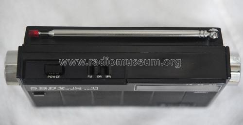
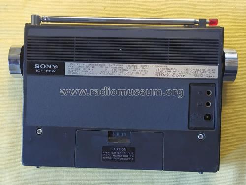
Antenna red tip is missing (broken antenna)

Antenna red tip is missing (broken antenna)


Thanks for the photos, Mr.Nemoka01!

Thanks for the photos, Mr.Nemoka01!

Thanks for the photos, Mr.Nemoka01!

Thanks for the photos, Mr.Nemoka01!


Haga clic en la miniatura esquemática para solicitarlo como documento gratuito.
- Numero de transistores
- 11
- Semiconductores
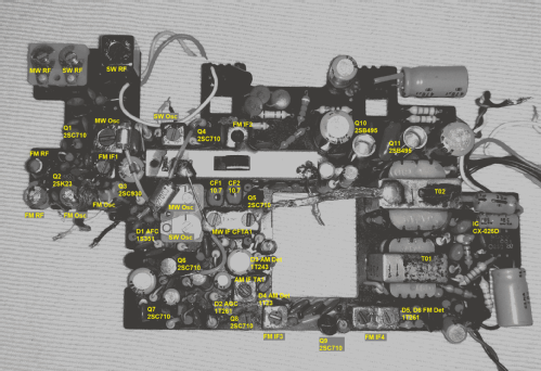
- 2SC710 2SC930 2SK23 2SC710 2SC710 2SC710 2SC710 2SC710 2SC710 CX-025 2SB495 2SB495 1S351 1T261 1T2432 1T23
- Principio principal
- Superheterodino en general; ZF/IF 455/10700 kHz
- Gama de ondas
- OM, OC y FM
- Tensión de funcionamiento
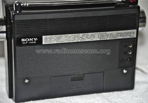
- Pilas + jack (etc.) para alimentación externa. / C: 3 x 1.5 / DC 4.5 Volt
- Altavoz
- Altavoz dinámico (de imán permanente) / Ø 9.2 cm = 3.6 inch
- Potencia de salida
- 1.1 W (unknown quality)
- Material
- Plástico moderno (Nunca bakelita o catalina)
- de Radiomuseum.org
- Modelo: IC-11 3Band IC+FET ICF-110W - Sony Corporation; Tokyo
- Forma
- Portátil de bolsillo , menor de 20cm.
- Ancho, altura, profundidad
- 188 x 136 x 52 mm / 7.4 x 5.4 x 2 inch
- Anotaciones
-
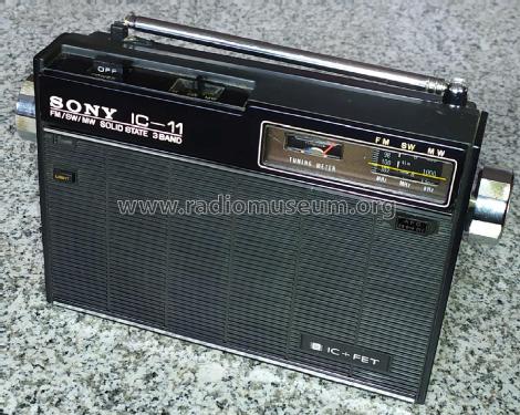
The Sony ICF-110W was the international version that was released after the earlier Japanese domestic ICF-110 and ICF-110B versions.
The ICF-110 and ICF-110B are identical, except the cabinet finish. The ICF-110 uses brushed aluminum on the sides and dial frame, while the ICF-110B is all black despite using the same aluminum material. The ICF-110W uses an all black cabinet like the ICF-110B.
Main features
- ICF-110 and ICF-110B
- FM: 76 - 90 MHz
- SW: 3.9 - 12 MHz
- MW: 530 - 1605 kHz
- ICF-110W
- FM: 87.5 - 108 MHz
- SW: 3.9 - 12 MHz
- MW: 530 - 1605 kHz
Fitted with: 10 Transitors, 1 FET, 1 IC.
- ICF-110 and ICF-110B
- Documentación / Esquemas (1)
- Selezione Radio-TV Dezember 1972
- Autor
- Modelo creado por Eduard Abfalterer. Ver en "Modificar Ficha" los participantes posteriores.
- Otros modelos
-
Donde encontrará 3913 modelos, 3773 con imágenes y 947 con esquemas.
Ir al listado general de Sony Corporation; Tokyo
Colecciones
El modelo IC-11 3Band IC+FET es parte de las colecciones de los siguientes miembros.
Museos
El modelo IC-11 3Band IC+FET se puede ver en los siguientes museos.
Contribuciones en el Foro acerca de este modelo: Sony Corporation;: IC-11 3Band IC+FET ICF-110W
Hilos: 5 | Mensajes: 8
The information on this Sony ICF-110 radio series seems to be scarce when looking to the Internet. Any additional information would be welcome.
According to some Japanese websites where some enthusiast fellows write about these series, there were three variants, with a short lifespan:
- ICF-110 released in 1969 and ceased in 1970
- ICF-110B released in 1970, ceased in 1971 with the release of the ICF-1100
- ICF-110W released in 1970, seems to be the internation version of the domestic 110B
The ICF-110 and ICF-110B were basically identical, but the 110 used a brushed aluminum body with black speaker grille, while the 110B and 110W were all black in color despite using the same aluminum material over the plastic case.
The 110 and 110B models share the same specifications with the color exception mentioned above:
- 1 x IC, 11 x TR (10 NPN Si, 1 JFET)
- FM/SW/MW 3-Band Superheterodyne
- Frequency Range:
- FM: 76-90MHz
- SW: 3.9-12MHz
- MW: 530-1605KHz
- IF:
- FM: 10.7MHz
- SW/MW: 455KHz
- Battery Supply: 1.5Vx3 UM-2, Size "C" Std Flashlight Battery
- Sony Corp. Tokyo Japan
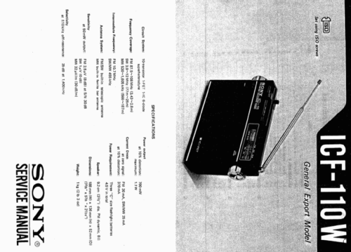
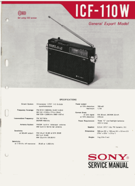
The 110W share the specifications with the 110B with the exception of the FM band. According to the service manual front cover, at least two versions were made, the USA Model and the General Export Model, both sharing the same specifications:
- 1 x IC, 11 x TR (10 NPN Si, 1 JFET)
- FM/SW/MW 3-Band Superheterodyne
- Frequency Range:
- FM: 87.5-108MHz
- SW: 3.9-12MHz
- MW: 530-1605KHz
- IF:
- FM: 10.7MHz
- SW/MW: 455KHz
- Battery Supply: 1.5Vx3 UM-2, Size "C" Std Flashlight Battery
- Sony Corp. Tokyo Japan
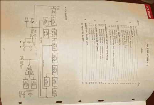
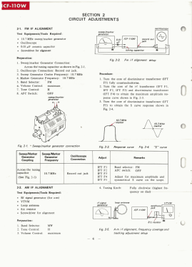
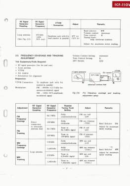
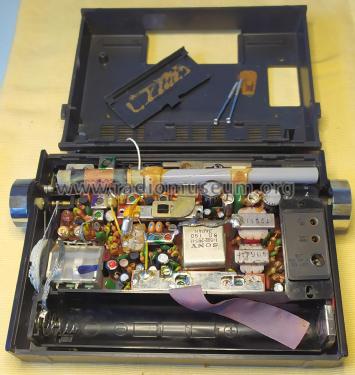
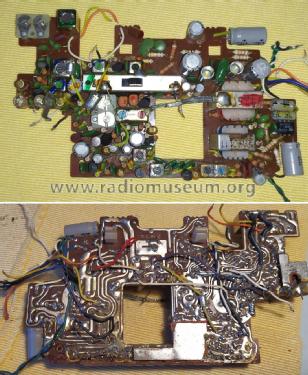
The service manual front cover lists respectable sensitivity figures for such a modest single conversion portable radio - FM 2.5uV (8dB) at S/N 30dB, SW 1uV (0dB), MW 32uV/m (30dB), for 50mW output. The large ferrite antenna taking up practically the entire width of the chassis certainly contributes to better MW reception.And the use of an extra FM RF amplifier stage with an FET certainly gives an advantage in FM reception.

Jose Mesquita, 02.Jul.21
Sony marketing did his job by proudly advertizing the use of Integrated Circuits in these two radio model variants (110B and 110W), along with other Sony series of the era, like the ICF-5500, ICF-110, ICF-500, among others.
The IC in question was a audio pre-amplifier/driver device containing three NPN Si transistors in DC coupled configuration, encapsulated in a DIP with 6 pins and designated as Sony CX-025.
The CX-025 6-pin DIP pinout is assigned inconsistently on different Sony models, depending on the IC version. There are public references at least to the CX-025, CX-025C, CX-025D, and CX-025E. Some versions pinout designate pin numbers above 6, despite the IC having only 6 pins.
Example of a CX-025C IC as seen on the ICF-110B and ICF-500S models:
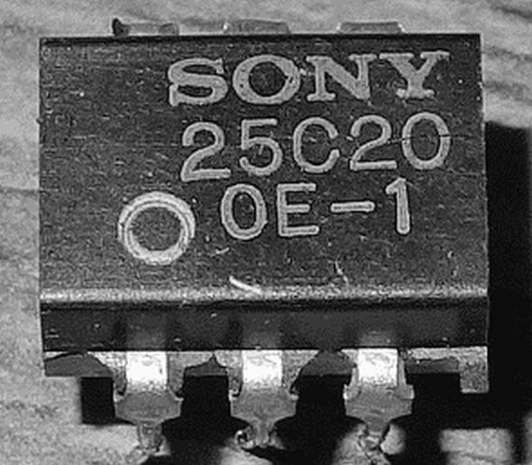
Example of a CX-025D IC as seen on the ICF-110W models:

On the ICF-500S the CX-025C pinout looks normal with pin numbers assigned from 1 to 6:


However, on the ICF-110W the CX-025D IC pinout numbering looks irregular with pin numbers above 6:

Additionally, the CX-025E used in the ICF-5500M not only uses pin numbers above 6, but also assigns different pinout as seen on the CX-025D, not to mention the now wrong symbol for an opamp:

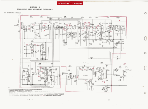
Comparing the three IC versions as used in the circuit diagrams, it looks that all share the same internal design, probably only differing in the gain and driver current.
Jose Mesquita, 01.Jul.21
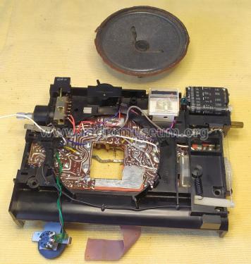
The loudspeaker is a genuine Japanese part with atention to detail - look to the position of the ground terminal, close to the ground plane of the PCB.
The miniature tone potentiometer is a replica of the larger volume pot, very well designed and built to last.
The two position power On/Off switch is a miniature brute force design, easily serviceable if needed.
And the Tuning Meter design where the rest position of the meter hand is on the right side of the scale - A japanese part as well.
Kind of 60's flavor in technological terms.


Jose Mesquita, 30.Jun.21
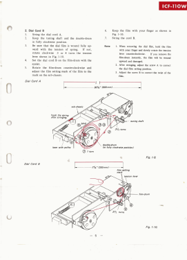
This is a beauty of a work by Sony.
Miniaturized tuning variable capacitor coupled to a double groove variable capacitor wheel, where the larger diameter wheel groove is controlled by the usual tuning shaft, and smaller diameter wheel groove drives the spring loaded winded tuning dial scale.


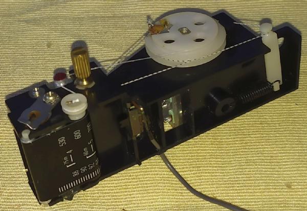


Variable capacitor, what a jewel, kind of hybrid between the classic air dielectric VC and a polyvaricon miniature VC. Inscriptions: Japan, HI-POLY CY41C 1-151-196-13 7137

The two condenser blade types.


Jose Mesquita, 29.Jun.21
My Sony ICF-110W unit is in very bad shape. Lots of battery corrosion inside, over the IF transformers shielding and metal front cover trims and paint.
Previous owner had the unit repaired, probably to fix a broken telescopic antenna that was replaced by a regular chinese antenna that was reshaped at the base to fit the back cover, resulting on a very bad job. The original antenna uses a special large base, ball style joint, and feature a nice red tip. While doing so, they also managed to brake the ferrite antenna that was badly glued on a amateur job. As if it was not enough , they used synthetic metallic varnish to seal all the shaft nuts and screws they could find, making further maintenance operations difficult.
As a result of such service operations, the volume pot was damaged as well, as the shaft was blocked with the varnish. A nightmare, making almost impossible to dismantle the radio in order to clean all the mess and try to restoite its operation.
Now, I know that there are no original spare parts anymore forr these vintage radios, at least without cannibalizing another unit, but I wonder if someone has leftovers from previous jobs that can part with?
Anyhow, I have gently forced the volume potentiometer out of the chassis frame, trying to not causing additional damage, and have dismantled the unit. Unfortunately the fragile old bakelite supporting the cursor was broken in the process. Used thinner to free the central shaft and later used the good old Araldite to join the parts. For the cursor support I used an easy-to-work piece of rigid plastic.
Volume pot components. Broken rotor support.

Chassis frame, showing the volume pot mount point. Reassembled volume pot. Apparently I was lucky as it seems to be working now. Still, I would like a new spare unit.

Jose Mesquita, 29.Jun.21