- País
- Australia
- Fabricante / Marca
- Standard Telephones and Cables Pty, Ltd (STC), Sydney
- Año
- 1936
- Categoría
- Radio - o Sintonizador pasado WW2
- Radiomuseum.org ID
- 169790
Haga clic en la miniatura esquemática para solicitarlo como documento gratuito.
- Numero de valvulas
- 7
- Principio principal
- Superheterodino con paso previo de RF; ZF/IF 175 kHz; 2 Etapas de AF
- Número de circuitos sintonía
- 7 Circuíto(s) AM
- Gama de ondas
- OM (onda media) solamente
- Tensión de funcionamiento
- Red: Corriente alterna (CA, Inglés = AC) / 200-250 Volt
- Altavoz
- Altavoz electrodinámico (bobina de campo) / Ø 8 inch = 20.3 cm
- Material
- Madera
- de Radiomuseum.org
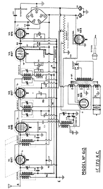
- Modelo: 613 Ch= 61 - Standard Telephones and Cables
- Forma
- Consola baja, patas más cortas del 50%.
- Anotaciones
-
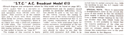
STC Model 613 is a six-valve receiver designed for broadcast coverage and operation from 200-250 volts AC mains.
This receiver is of the console type and is fitted with three controls, these being for volume, tuning, and tone (continuous). The loudspeaker fitted is an 8-inch unit with field-coil resistance of 2,500 Ω. The external features are completed by the provision of a type 6E5 tuning indicator.
The chassis fitted to this model is known as “type 61”.
The design of this receiver is fairly straightforward & its analysis should present no particular difficulties. Atten should be paid to the fact that all the valves (except tuning indicator) are of the metal envelope series, and it should be remembered that if for any reason, replacement of any of these “radio” valves with octal-glass types becomes necessary, realignment of the tuning circuits associated with that valve (or valves) will be essential. Finally, care should be taken to see the power cord connector (SP 3106) is inserted into its socket correctly (i.e., with the marking to suit the AC supply voltage facing upwards).
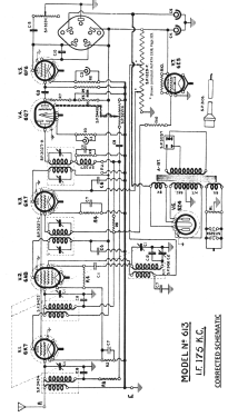
*SPECIAL NOTE.
There is apparently a draughtsman’s error in the circuit diagram of this model, in the oscillator plate supply is shown as being obtained from the lower voltage tapping on the voltage divider than that which feeds the screens. It will be found that relative positions of the clips are reverse to those shown; in which case no attempt should be made to change the connections over to the positions shown in the diagram.
Radio Trade Annual 1938, Page 329.
*See modified schematic.
- Precio durante el primer año
- 30.00 Aus£
- Documentación / Esquemas (1)
- Radio Trade Annual 1938 P327.
- Autor
- Modelo creado por Stuart Irwin. Ver en "Modificar Ficha" los participantes posteriores.
- Otros modelos
-
Donde encontrará 615 modelos, 264 con imágenes y 303 con esquemas.
Ir al listado general de Standard Telephones and Cables Pty, Ltd (STC), Sydney