- Paese
- Australia
- Produttore / Marca
- Standard Telephones and Cables Pty, Ltd (STC), Sydney
- Anno
- 1936
- Categoria
- Radio (o sintonizzatore del dopoguerra WW2)
- Radiomuseum.org ID
- 169790
Clicca sulla miniatura dello schema per richiederlo come documento gratuito.
- Numero di tubi
- 7
- Principio generale
- Supereterodina con stadio RF; ZF/IF 175 kHz; 2 Stadi BF
- N. di circuiti accordati
- 7 Circuiti Mod. Amp. (AM)
- Gamme d'onda
- Solo onde medie (OM).
- Tensioni di funzionamento
- Alimentazione a corrente alternata (CA) / 200-250 Volt
- Altoparlante
- AP elettrodinamico (bobina mobile e bobina di eccitazione/di campo) / Ø 8 inch = 20.3 cm
- Materiali
- Mobile in legno
- Radiomuseum.org
- Modello: 613 Ch= 61 - Standard Telephones and Cables
- Forma
- Console, con gambe d'appoggio basse (< 50%).
- Annotazioni
-
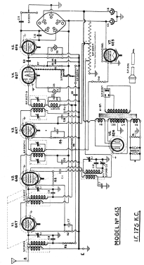
STC Model 613 is a six-valve receiver designed for broadcast coverage and operation from 200-250 volts AC mains.
This receiver is of the console type and is fitted with three controls, these being for volume, tuning, and tone (continuous). The loudspeaker fitted is an 8-inch unit with field-coil resistance of 2,500 Ω. The external features are completed by the provision of a type 6E5 tuning indicator.
The chassis fitted to this model is known as “type 61”.
The design of this receiver is fairly straightforward & its analysis should present no particular difficulties. Atten should be paid to the fact that all the valves (except tuning indicator) are of the metal envelope series, and it should be remembered that if for any reason, replacement of any of these “radio” valves with octal-glass types becomes necessary, realignment of the tuning circuits associated with that valve (or valves) will be essential. Finally, care should be taken to see the power cord connector (SP 3106) is inserted into its socket correctly (i.e., with the marking to suit the AC supply voltage facing upwards).
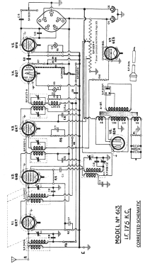
*SPECIAL NOTE.
There is apparently a draughtsman’s error in the circuit diagram of this model, in the oscillator plate supply is shown as being obtained from the lower voltage tapping on the voltage divider than that which feeds the screens. It will be found that relative positions of the clips are reverse to those shown; in which case no attempt should be made to change the connections over to the positions shown in the diagram.
Radio Trade Annual 1938, Page 329.
*See modified schematic.
- Prezzo nel primo anno
- 30.00 Aus£
- Letteratura / Schemi (1)
- Radio Trade Annual 1938 P327.
- Autore
- Modello inviato da Stuart Irwin. Utilizzare "Proponi modifica" per inviare ulteriori dati.
- Altri modelli
-
In questo link sono elencati 616 modelli, di cui 273 con immagini e 306 con schemi.
Elenco delle radio e altri apparecchi della Standard Telephones and Cables Pty, Ltd (STC), Sydney