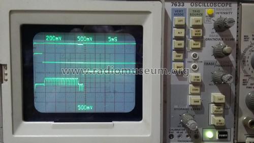
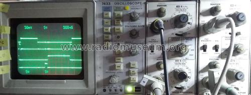
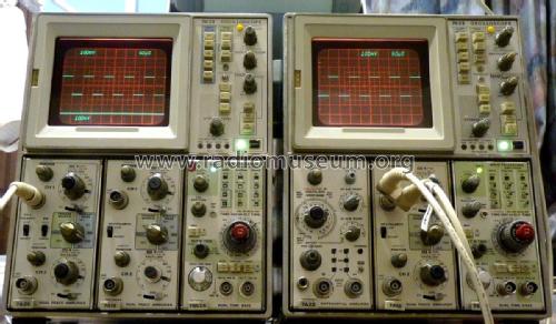
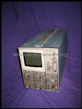
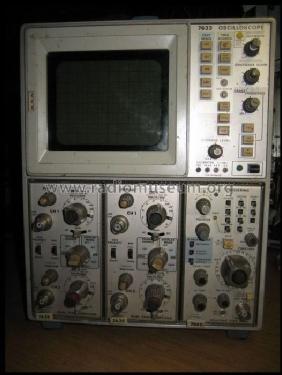
Oscilloscope 7633
Tektronix; Portland, OR
- Land
- USA
- Hersteller / Marke
- Tektronix; Portland, OR
- Jahr
- 1974–1990
- Kategorie
- Service- oder Labor-Ausrüstung
- Radiomuseum.org ID
- 147705
Facade tektronix 7633


- Anzahl Röhren
- 1
- Röhren
- 154-0721-00
- Anzahl Transistoren
- Halbleiter vorhanden.
- Halbleiter
- Wellenbereiche
- - ohne
- Betriebsart / Volt
- Wechselstromspeisung / 100; 110; 120; 200; 220; 240 Volt
- Lautsprecher
- - Für Kopfhörer oder NF-Verstärker
- Material
- Metallausführung
- von Radiomuseum.org
- Modell: Oscilloscope 7633 - Tektronix; Portland, OR
- Form
- Tischmodell, Zusatz nicht bekannt - allgemein.
- Abmessungen (BHT)
- 220 x 290 x 600 mm / 8.7 x 11.4 x 23.6 inch
- Bemerkung
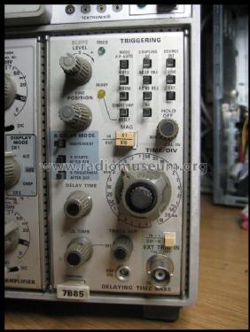
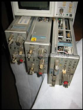
- 2 Kanal Storage Oscilloscope; 100MHz; Schirm: 105 x 85 mm; Bausteinbestückung : 2x 7A26 + 7B85A Doppelzeitbasis
- Nettogewicht
- 20 kg / 44 lb 0.8 oz (44.053 lb)
- Originalpreis
- 4,725.00 $
- Literaturnachweis
- - - Manufacturers Literature (Tektronix catalog 1975, TekScope Mar/Apr 1974)
- Autor
- Modellseite von Roland Aust angelegt. Siehe bei "Änderungsvorschlag" für weitere Mitarbeit.
- Weitere Modelle
-
Hier finden Sie 388 Modelle, davon 376 mit Bildern und 92 mit Schaltbildern.
Alle gelisteten Radios usw. von Tektronix; Portland, OR
Sammlungen
Das Modell Oscilloscope befindet sich in den Sammlungen folgender Mitglieder.
Forumsbeiträge zum Modell: Tektronix; Portland,: Oscilloscope 7633
Threads: 1 | Posts: 1
A 1000 cm/µs storage oscilloscope
Source: Tekscope Vol 6 Number 2 Mar/Apr 1974
 |
Just two years ago laboratory storage scopes with stored writing speeds from 100 cm/µs to 400 cm/µs were introduced. The fastest of these instruments could store single events having a risetime of 9 ns and 3.5 cm in amplitude. Now a new storage scope, the TEKTRONIX 7633, moves this performance up to 1000 cm/µS to capture single risetimes of 3.5 ns at an amplitude of 3.5 cm. To relate this performance to your measurements let's review the speed needed for recording single sinewaves and steps. |
Writing speed relationships
For sinewaves the maximum writing speed. WS, is measured in terms of frequency, f, and amplitude, As, as in Equation 1

Equation 2 describes the maximum writing speed of the vertical edge of a pulse in terms of amplitude, As, and 10 - 90% risetime, Tr . The value of k ranges from 0.8 for a linear ramp, to 2.2 for single-pole RC response. A k value of 1.0 is suitable for typical step responses limited by a few poles.
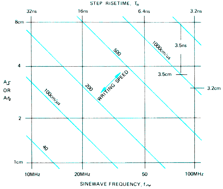
Fig. 1. This nomograph shows a writing speed of 1000 cm/µS will display a 35 ns risetime, 33 cm in amplitude and a 100 MHz sine wave of 3.2 cm.
A nomograph of Equations 1 and 2 is given in Figure 1, for the 10 MHz to 100 MHz range. Note that a 1000 cm/µs stored writing speed can record a 100 MHz. sinewave 3.2 cm in amplitude, or a 3.5 ns risetime of 3.5 cm amplitude. Front the nomograph one might say that 1000 cm/µs is 100 MHz storage, 100 cm/µs is 10 MHz storage. etc. (specifically for signals 3.2 cm in amplitude).
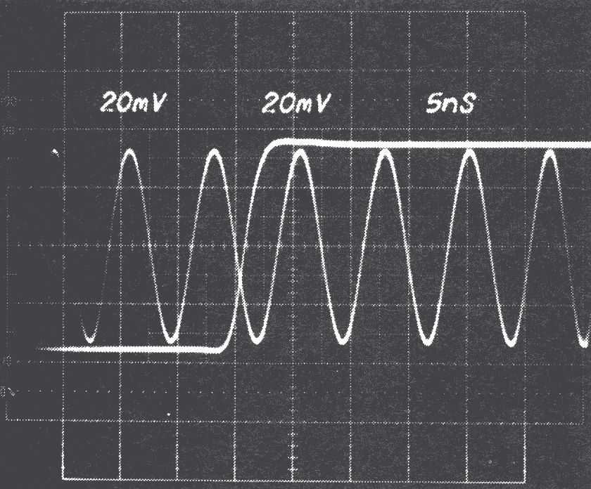
Fig. 2. A stored display of a sine wave and step of equal maximum speed. Note relative amplitude.
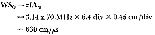
A sinewave and step of equal maximum speed are shown in Figure 2. The sinewave frequency is 70 MHz, and the step risetime of 5 ns corresponds to a system bandwidth of 70 MHz (from Tr = 0.35/f). The amplitude ratio, As/Ar equals 3.5/3.2. The displayed writing speed is:
Thus far we have neglected the horizontal, or time base, component of speed. In Figure 2. where the horizontal speed is one-sixth that of the maximum vertical speed, only a 1% increase in speed results from including the horizontal component. If the time base speed is doubled, to one-third the maximum vertical speed, the increase goes up to 5%. These small corrections permit neglecting the horizontal component for most maximum speed considerations.
Although sinewaves are not typical of signals we normally record, they are used for speed verification for a couple of reasons --an accurate speed is easily set up by selecting frequency and amplitude; and speed through an area is verified in a single pass since the maximum speed occurs twice each cycle.
Now that we can relate the writing speed of the scope to the signals it will capture, let's look at the operation of the storage crt used in the 7633.
The transfer storage crt
The crt used in the 7633 is, in principle, a transmission-modulation reading direct-view storage tube. In more common terminology we know it as halftone transmission storage or variable persistence storage. One of the undesirable characteristics of the halftone transmission storage tube is that unwritten areas of the storage target begin to fade positive due to positive ion generation in the flood electron system of the tube. As a result, after a few minutes, signals can no longer be distinguished from the bright background.
To overcome this limitation in view time, we have added another storage target to the conventional halftone storage tube (see Figure 3).1 The two targets are called the fast target and storage target, respectively.
The image is first written on the fast target and is then transferred to the storage target which, by proper selection of operating voltage, can be operated in either a variable persistence mode or a bistable mode. In the bistable mode the image can be stored until you choose to erase it.
Perhaps at this point we should clarify the use of the terms "variable persistence" and "halftone." The crt can display shades of gray, but since both the instrument and the crt are optimized for high-speed variable persistence performance rather than multi-tonal performance, "variable persistence" is the more appropriate term.

The 7633 Storage Oscilloscope

Fig. 3. The transfer storage tube contains two storage targets to achieve fast writing speeds with long viewing times.
Writing speed and view time
There is a direct relationship between writing speed and view time. To better understand this relationship let's look at the factors determining the writing speed of a storage crt as shown in Equation 3.
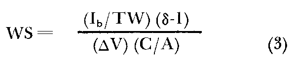
Where:
WS is stored writing speed.
Ib/TW is the current density at the target-beam current, Ib, , per trace width, TW
(δ . I) is the net positive electron charge for each electron arrival-secondary emission yield, δ, minus the arriving electron.
ΔV is the minimum voltage change on the target surface that results in writing for the specified area.
C/A is the capacitance of the target surface to the target mesh per unit area.
For further discussion, the parameters ΔV and C/A are combined to ΔVC/A, the charge sensitivity of the target.
We noted earlier that view time is limited by the number of residual gas atoms near the storage target, being ionized by flood electrons and collecting on the target surface charging it positive. The signal waveform "washes out" as the background increases in brightness until the signal can no longer be seen. The faster the writing beam moves across the target, the less the charge placed on the target, and the more rapidly the trace is obscured by ion activity.
Trading writing speed for view time
Figure 4 shows some of the writing speed versus view time trading to be made in using a given variable persistence scope and in choosing a particular at target. Note that a range of writing speed and view times are available. At the highest writing speed we see the sensitivity limit where it is no longer possible to achieve more speed by accepting less view time.

Fig. 4. Graph showing writing speed versus viewing time for two different storage targets.
The operating point along the WS and VT curve is determined by the storage mesh voltage. The storage level control, a front-panel control on TEKTRONIX variable persistence scopes, permits you to move down the curve by decreasing the storage mesh voltage, for a longer view time as less writing speed is needed.
As the fast target curve in Figure 4 suggests, it is possible to make targets with higher writing speeds. However, when this speed increase is a result of improved charge sensitivity, the rate of positive ion charging is increased and the view time suffers proportionately.
The charge sensitivities of the fast and storage targets in the 7633 crt are 5 picocoulombs/cm2 and 500 picocoulombs/cm2, respectively, giving the fast target a 100:1 charge sensitivity advantage. Looking at the fast target performance in Figure 4 we see a writing speed above 1000 cm/µs can be achieved. But the view time is below 1 second — much too short for useful viewing. It is evident we have traded too much view time for writing speed.
Transfer, don't trade
This is where the transfer technique becomes useful. During the 0.1 second following waveform capture by the fast target, the image is transferred from the fast target, to the storage target. A gain of about 1000X in the stored charge image accompanies this transfer. Now at the fastest writing speed of 1000 cm/µs we have a minimum view time of at least 30 seconds which is more than adequate for most high-speed applications.
New modes, new speeds
The fastest stored writing speed of the 7623 storage oscilloscope introduced in mid-1972 is 100 cm/µs (200 cm/µs for Option 12). Using basically the same crt, how is writing speed increased to 1000 cm/µs? This is accomplished with two new modes of operation—reduced scan selection and fast variable persistence.
In the reduced scan mode, the operating voltage on the crt write gun is increased from 1500V to 3000V. Referring to Equation 3, Ib/TW increases by about 2.5X and δ . I is higher by about 1.6X for a total increase in speed of 4X. The useful display area is 8 x 10 div (0.45 cm/div) in this mode.
Operating the storage target in the fast variable persistence mode rather than the fast bistable mode as in the 7623, provides a speed improvement of 3X. Referring again to Equation 3, the ΔV of the fast target is reduced by 3X due to the new operation of the storage target. This is because less change is required for storage, and gray scale signal levels are not discarded.
Combining the reduced scan with fast variable persistence, a typical speed increase of 12X is realized over the full-scan, fast-bistable mode of operation.
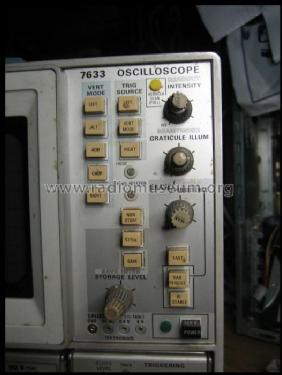
The 7633 storage controls
To conclude our discussion let's consider briefly the front panel controls for the 7633 (See Figure 5). A set of three push buttons selects display modes of NON-STORE, STORE and SAVE. The SAVE monde has three uses:
- To prevent loss of the captured signal. Erase and sweep cycles are locked out in this mode.
- For extended retention of the variable persistence displays. Turning the SAVE INTENSITY down reduces the flood electron current and extends the view time in proportion to the reduced intensity. It can be turned off for hours of retention.
- To set up a "Babysitting" mode which will auto¬matically give the above two performances after a future event. The "Babysitting" mode is entered by pressing the SAVE push button after ERASE.
Another set of push buttons selects storage modes of FAST. VAR PERSIST and BISTABLE. Note that the PERSISTENCE and ERASE controls are located together and provision is made for periodic erase. This can be used in three ways:
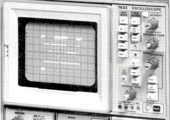
Fig. 5. Front-panel controls permit a choice of storage modes and operating conditions for optimum performance on your application.
- To periodically erase independent of the number of waveforms stored during the period.
- To accept one waveform for each erase period (time base set to single sweep).
- To erase at the end of sweep (or sweeps). The period is adjusted to end during the sweep and the erase cycle is delayed to the end of that sweep.
The STORAGE LEVEL. control, as mentioned previously, permits us to decrease the storage mesh voltage for longer view times as less writing speed is needed. The FAST LEVEL. CENTER adjustment is provided to separately adjust the fast mesh voltage for the desired tracking of the STORAGE LEVEL on the two meshes.
The REDUCED SCAN switch operates independent of the display and storage modes and permits choosing full-scan operation when the last 4X writing speed increase is not needed. It is also convenient to set up the reduced scan display in nonstore before going to storage operation.
All of the 7000 Series advantages
In addition to high-speed versatile storage, the 7633 offers all of the advantages of the 7000Series Oscilloscopes. Crt readout is standard equipment and you can select from 30 different 7000-Series plug-ins to "custom tailor" the instrument to your job and expand its capabilities as the need arises.
Acknowledgments
The author thanks everyone on the 7633 project for their dedication in making this a significant product.
1 “Three New Instruments, Three Kinds of Storage” Tekscope, July, 1972
Anlagen
- TEKSCOPE74_1_Fig1 (16 KB)
- TEKSCOPE74_1_Fig2 (64 KB)
- TEKSCOPE74_1_Fig3 (32 KB)
- TEKSCOPE74_1_Fig4 (7 KB)
- TEKSCOPE74_1_Fig5 (73 KB)
- TEKSCOPE74_1_7633 (83 KB)
Pius Steiner, 24.Jan.14