- Country
- United States of America (USA)
- Manufacturer / Brand
- Tele-Tone Radio Corp., Tele-Tone Co. Inc.; New York (NY)
- Year
- 1960 ?
- Category
- Broadcast Receiver - or past WW2 Tuner
- Radiomuseum.org ID
- 167978
-
- alternative name: Teletone
Share Freely

Share Freely
Share Freely

Share Freely

- Number of Tubes
- 5
- Main principle
- Superheterodyne (common); ZF/IF 455 kHz
- Tuned circuits
- 4 AM circuit(s)
- Wave bands
- Broadcast only (MW).
- Power type and voltage
- AC/DC-set / 117 Volt
- Loudspeaker
- Permanent Magnet Dynamic (PDyn) Loudspeaker (moving coil) / Ø 4 inch = 10.2 cm
- Power out
- 1 W (unknown quality)
- Material
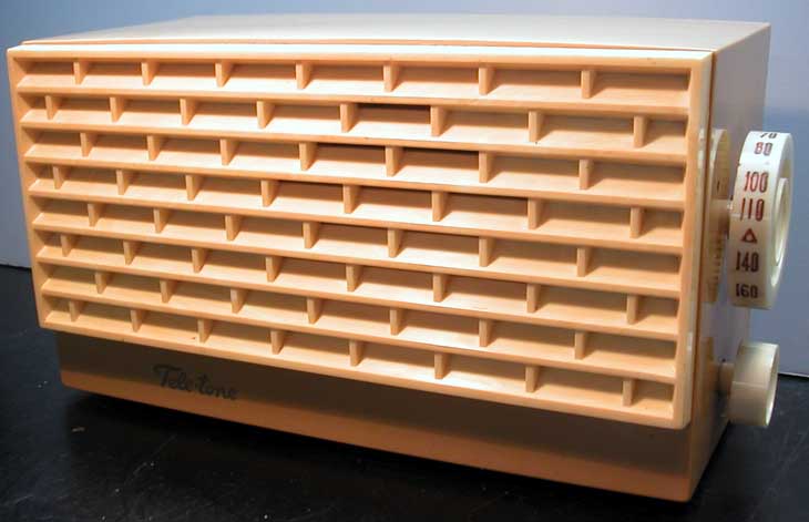
- Plastics (no bakelite or catalin)
- from Radiomuseum.org
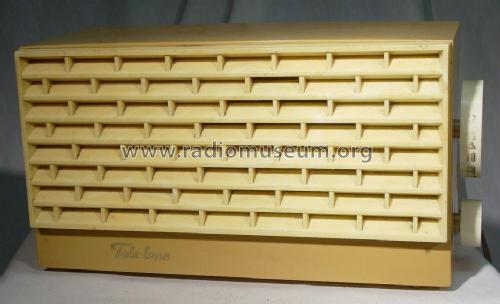
- Model: 990 - Tele-Tone Radio Corp., Tele-
- Shape
- Tablemodel without push buttons, Mantel/Midget/Compact up to 14
- Dimensions (WHD)
- 5 x 5.5 x 10 inch / 127 x 140 x 254 mm
- Notes
- This case was also used by Firestone and Stromberg-Carlson to make an AM set. This case was also used by Teletone for the FM-only model 1000.
- Net weight (2.2 lb = 1 kg)
- 2 lb (2 lb 0 oz) / 0.908 kg
- Literature/Schematics (1)
- AntiqueRadio.com, my collection
- Author
- Model page created by Joe Sousa. See "Data change" for further contributors.
- Other Models
-
Here you find 168 models, 77 with images and 128 with schematics for wireless sets etc. In French: TSF for Télégraphie sans fil.
All listed radios etc. from Tele-Tone Radio Corp., Tele-Tone Co. Inc.; New York (NY)
Forum contributions about this model: Tele-Tone Radio Corp: 990
Threads: 2 | Posts: 5
Fellow Radiophiles,
A couple of years ago, I played with the idea of eliminating the cathode bias resistor and capacitor from the 50C5 in a Toptone Topline 5M-100 AC-DC set, by taking the bias for the 50C5 grid from the local oscillator grid of the 12BE6. This worked very well, but I had never seen it done in a commercial radio.
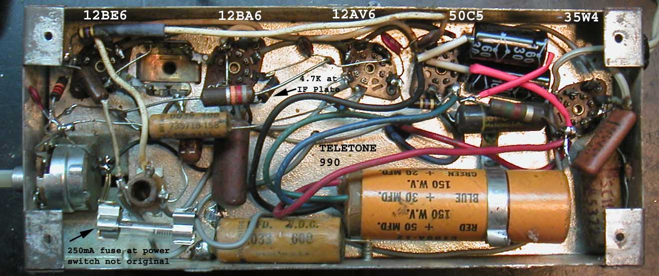
As I was looking inside my Teletone 990, I noticed that the cathode of the 50C5 was hard grounded. I had not noticed this before because I don't have a schematic. Then I noticed that the 50C5 grid was biased with a long white wire to a 470k resistor soldered to the local oscillator grid at pin1 of the 12BE6 pentagrid converter. This resistor is visible at the upper left of this photo. There is also a small red ceramic filter capacitor at the 50C5 grid pin2 to keep the LO signal out of the 50C5. Also note that wiring the 470k at the 12BE6 keeps parasitic capacitance to the oscillation grid pin1 to a minimum.
One concern with this efficient method of 50C5 grid bias, is that the voltage stay reasonably constant as the LO frequency is varied when the radio is tuned from one end of the dial to the other. This set did pretty well in this respect. The DC bias voltage provided by the 12BE6 grid varied only from -7.3V to -9V, as I changed the tuning from one end of the band to the other.
I made an adapter to replace the 12BE6 pentagrid converter with a 12BA7 with twice the conversion transconductane to improve the performance of this set. The DC bias variation over the tuning range, for the 12BA7 was even less, from -8.5V to -9.5V.
Flattening the LO DC self bias over the tuning range can be done by controlling the Q of the oscillating circuit with series or paralel resistance, which affect Q differently at high vs low frequencies. The self bias is proportional to the oscillation amplitude at the grid, and it is a little less than half the p-p amplitude.
If the oscillation is too strong at the high end of the dial, then some parallel resistance is needed to lower the amplitude at the high end. If the oscillation is too strong at the low end of the band, then some series resistance with the LO tuning capacitor or tuning coil is needed.
Another way to flatten the amplitude over the tuning range is to change the value of the usual 22k grid bias resistor. Increasing the value of the 22k resistor increases oscillations more at the high end than at the low end. Reducing the 22k resistor has the opposite effect.
The amplitude of oscillation can be manipulated over the tuning range because the reactance of the L and C components varies over frequency.
For a set that is capacitance tuned, the reactance of the fixed inductor is lowest at the low end of the dial, but the reactance of the tuned capacitor is also lowest here, because the capacitance is greatest at the low end. This means that the Q of this tank circuit will be more sensitive to series resistance at the low end of the dial.
At the High end of the dial, the fixed inductor reactance has doubled as the LO frequency increased from 1MHz (455kHzIF+540kHzRF) at the low end to 2MHz (455kHzIF+1540kHzRF) at the high end. The reactance of the capacitor has dropped much more, because the capacitance was also greatly reduced at 2MHz to 1/4 of the 1MHz value. Now we have a much higher impedance tank circuit, that is much more sensitive to shunt resistance.
Regards,
-Joe
Joe Sousa, 02.Mar.10
Fellow Radiophiles,
Sometimes it is fun to put an unreasonable amount of effort into a repair.
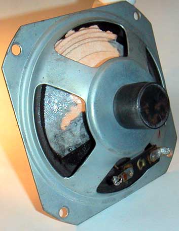
One such case is the repair to the paper cone of the 4" speaker in this inexpensive American AC/DC set.
This cone had a hole covering almost one third of the area that was probable the result of rodent damage.
The speaker could have been easily replaced, but it was more fun to repair it.

The repair consisted in replacing the missing paper with paper from a common coffee filter. I stiffenned and glued the coffee filter paper with clear acrylic nail polish.
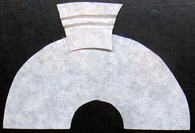
I rebuilt the inner section of the cone first, with a semicircle of coffee filter paper. I cut the paper to come up to the edge of the speaker "surround".
I applied this section to the back of the existing cone with acrylic nail polish and let it dry out.
Now I had an arc shaped gap where the surround still had to be rebuilt.
Then I cut a wider arc of coffee filter paper to overlap with the first section of coffee filter paper. The diameter of this arc must be significantly wider than the final diameter of the speaker to allow for the folds in the "surround".
 I drew several arcs in the coffee filter arc to mark the location for the creases, and left about 1/4" overlap with the inner coffee filter rebuilt section.
I made the creases on the arc before applying the arc to the speaker with a sharp cylindrical edge that I rolled over a bed of soft paper.
After applying the coffee filter paper arc with acrylic nail polish, I let it dry and trimmed off the excess past the edge of the speaker.
The surround was gently worked in place while it was wet with the acrylic nail polish.
The overlap flap from the curround section was tucked under the central section of the rebuilt cone that was already dry and set in place.

I chose to leave the paper in white because I was very happy with the repair, and making the paper black was not otherwise justified in this case.
While I was stiffening the coffee filter paper I applied a low frequency to the speaker and listened for rattles. I had to trim some loose ends and make sure there were no gaps in the glue.
This set arrived with a lot of rust, but a sanding head on the mini drill cleared it up.

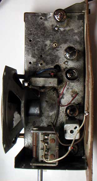
There was very little wrong with this set: a broken power switch and a few bad capacitors. I also added a 250mA MDL slow blow fuse at the power switch as an added measure of safety. The internal ground is AC-coupled to the chassis with 0.05uF. One unusual feature in this, otherwise very modest set, is the fully enclosed metal chassis with a metal bottom cover.

The grill is wide enough to show the speaker repair.
But the speaker is out of sight in normal use.
I bought this AM set while I was looking for the FM version, a Teletone model 1000. I was oriented in my search with help from our fellow radiophiles at www.antiqueradios.com.
Still looking for the FM version.
Regards,
-Joe
Joe Sousa, 08.Feb.10