- País
- Alemania
- Fabricante / Marca
- Telefunken Deutschland (TFK), (Gesellschaft für drahtlose Telegraphie Telefunken mbH
- Año
- 1955/1956
- Categoría
- Radio - o Sintonizador pasado WW2
- Radiomuseum.org ID
- 135007
US model has full FM coverage (88-108 MHz)
Haga clic en la miniatura esquemática para solicitarlo como documento gratuito.
- Numero de valvulas
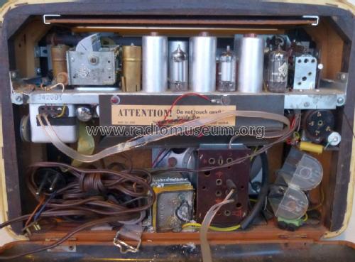
- 7
- Principio principal
- Superheterodino en general; ZF/IF 460/10700 kHz; Modelo de Exportacion
- Número de circuitos sintonía
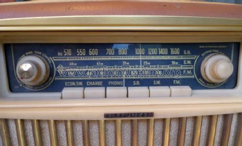
- 7 Circuíto(s) AM 11 Circuíto(s) FM
- Gama de ondas
- OM, OC y FM
- Tensión de funcionamiento
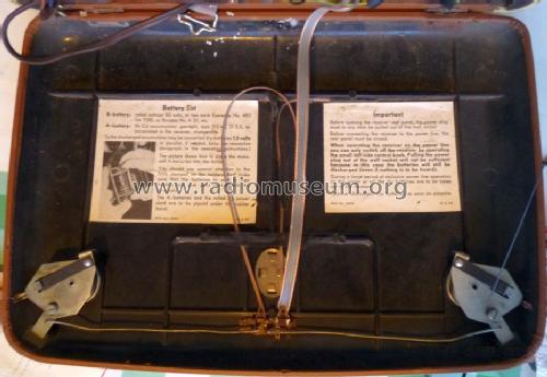
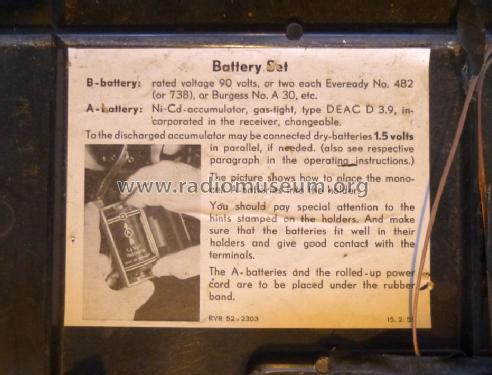
- Red / Baterías o pilas / AC 110; 125; 150; 220 / 1.5 & 90 Volt
- Altavoz
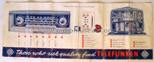
- Altavoz elíptico de imán permanente.
- Material
- Materiales diversos
- de Radiomuseum.org
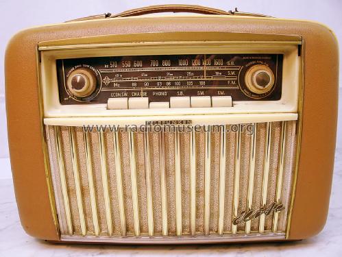
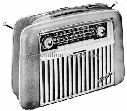
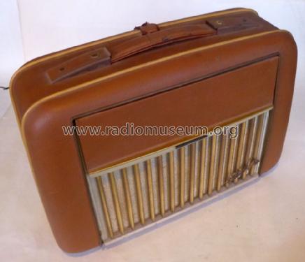
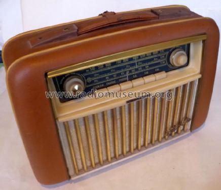
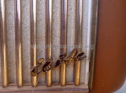
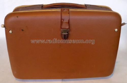
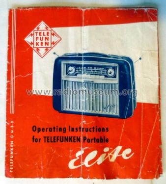
- Modelo: Elite - Telefunken Deutschland TFK,
- Forma
- Portátil > 20 cm (sin la necesidad de una red)
- Ancho, altura, profundidad
- 380 x 270 x 150 mm / 15 x 10.6 x 5.9 inch
- Anotaciones
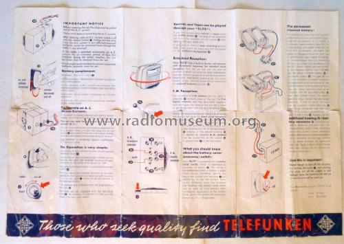
- The Telefunken model "Elite" is an export version of Telefunken Bajazzo, imported and distributed in the USA by American Elite, Inc., 7 Park Ave., New York, NY. It therefore has broadcast band, two SW and FM instead of LW, broadcast, SW and FM. It uses a Nickel-cadmium storage battery. Be careful and take it away because they often leak after such long time. Photofact shows on the title page the possible voltages but in the part list it shows a transformer for 117 volts primary. The speaker is 4" x 6" in diameter.
- Peso neto
- 7.5 kg / 16 lb 8.3 oz (16.52 lb)
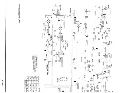
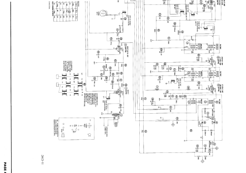
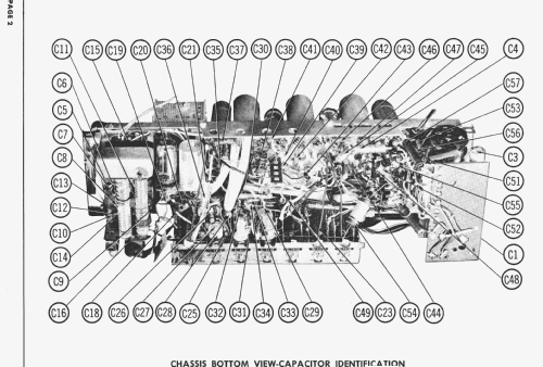
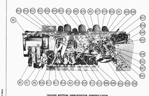
- Documentación / Esquemas (1)
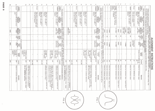
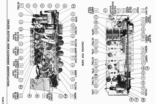
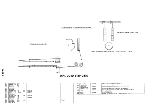
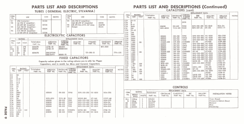
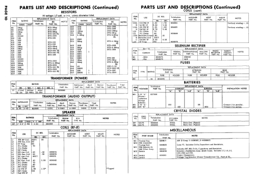
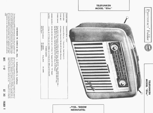
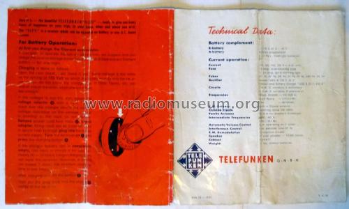
- Photofact Folder, Howard W. SAMS (Date 1-57, Set 343, Folder 11)
- Autor
- Modelo creado por Ernst Erb. Ver en "Modificar Ficha" los participantes posteriores.
- Otros modelos
-
Donde encontrará 3582 modelos, 3169 con imágenes y 2126 con esquemas.
Ir al listado general de Telefunken Deutschland (TFK), (Gesellschaft für drahtlose Telegraphie Telefunken mbH
Colecciones
El modelo Elite es parte de las colecciones de los siguientes miembros.
Contribuciones en el Foro acerca de este modelo: Telefunken: Elite
Hilos: 1 | Mensajes: 1
Fellow Radiophiles,
I found an error in the Sams Photofact FM IF alignment instructions for the Telefunken Elite.
The error is in the instructions at step 18:
![]()
This step is under the IF instructions, but it is not an IF adjustment. It should be done as the first step of the FM front end alignment.
The purpose of this step is to balance the front end mixing bridge to minimize antenna radiation of the Local FM oscillation produced by the DC90.
The adjustment is done with an insulated tool at the trimmer capacitor marked by A24. The following excerpt is from the Photofact instructions and is correct.

The measurement is done with an VHF RF voltmeter at the FM antenna terminals, or with an oscilloscope with >100MHz bandwidth and mV sensitivity.
Turn A24 to minimize the presence of local oscillator frequency at the antenna, with the dial set to 98MHz. The local oscillator will be running at 98MHz+10.7MHz=108.7MHz.
For comparision with correct instructions, the following excerpts show the equivalent trim for the Telefunken Bajazzo 55, which has a very similar chassis. The trim is done at C under similar conditions, with the dial centered at 94MHz.

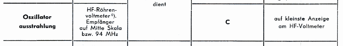
I made the adjustment with a Tektronix 7854 oscilloscope and 7A26 vertical plug-in. I coupled the 240 Ohm FM antenna with a ballun transformer to step down to 60 Ohms, and terminated the 2 foot 50 Ohm coax cable with 50 Ohms at the scope. The Local oscillator leakage seen at the scope varied from an optimum of 10mVp-p, to 200mVp-p when the trimmer was rotated for worst leakage.
The exact impedance and termination for this measurement are not important. I gave them here to support the circumstances of the voltage measurements. The important thing is to minimize the radiated oscillation. You will also notice that the leakge is not constant throught the dial, and this is the reason why the 98MHz center frequency is chosen for the adjustment.
Regards,
-Joe
Joe Sousa, 30.Apr.10