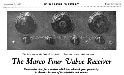
The Marco Four Valve Receiver
Wireless Weekly Magazine, Sydney
- Paese
- Australia
- Produttore / Marca
- Wireless Weekly Magazine, Sydney
- Anno
- 1926
- Categoria
- Kit, scatola di montaggio (parti sfuse e istruzioni o solo istruzioni di montaggio)
- Radiomuseum.org ID
- 332262
Clicca sulla miniatura dello schema per richiederlo come documento gratuito.
- Numero di tubi
- 4
- Principio generale
- A reazione (con rigenerazione)
- Gamme d'onda
- Solo onde medie (OM).
- Tensioni di funzionamento
- Batterie (di accumulatori e/o a secco) / 4½ & 6 & 2 x 45 Volt
- Altoparlante
- - Questo apparecchio richiede altoparlante/i esterno/i.
- Materiali
- Bachelite, valvole visibili
- Radiomuseum.org
- Modello: The Marco Four Valve Receiver - Wireless Weekly Magazine,
- Forma
- Chassis o in scatola da montaggio
- Annotazioni
-
The Marco Four Valve Receiver
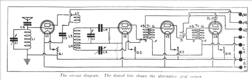
The distance getting proclivities of the straight detector Reinartz is well known all the world over. Until recently all attempts to add radio frequency were never very successful. It remained to Mr. D. L. Pendelton, Consulting Engineer to Martin Copeland Co., the makers of Marco radio material, to devise a system whereby radio frequency could be successfully applied to the Reinartz. Several different systems were tried out and discarded until finally the circuit published here was produced.
Looking at this circuit the usual Reinartz will be recognised in coils L 3 and L 4, tuned with variable condensers C2 and C . Preceding this is found the RF valve (VI.) the coil L2 being the coupling coil transferring the RF energy to L3, and the V2, which is the detector tube. Now the greatest difficulty connected with RF is stabilisation, hence the potentiometer in the tuned anode circuit, and neutralization in the Neutrodyne. Unless some means of controlling oscillation is provided, considerable difficulty is met with in radio frequency amplification, thereby rendering it almost useless. The method adopted by Pendleton is simple yet particularly effective. It is always desirable with radio frequency to transfer as much energy as is possible without impairing selectivity, causing uncontrollable oscillation in the RF valve. The method adopted in this instance is the coupling between the RF plate coil (L2) and the detector grid coil (L3). However, without going into the theory of this matter, be assured that this receiver is wonderfully selective, and although there are 3 condensers to tune, it is quite simple to bring in the different stations.
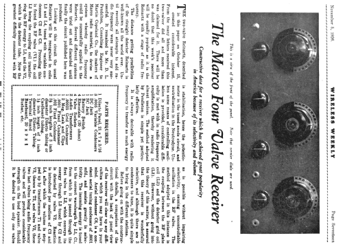
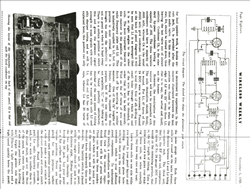
Before going on with the constructional details, a comparison of the circuit with the back of panel view of the receiver will clear up any difficulties which you may have in your mind. Aerial condenser C6, is a constant aerial tuning condenser of .0001 mfd., and assists greatly in selectivity. The incoming energy is tuned to the correct wavelength by LI, Cl, from which it is passed through the first valve to L 2, which conveys its energy through L3 tuned by C2 and is detected by valve V2. Reaction is introduced per medium of C3 and L4, after which the volume is stepped up by transformers T1 and valve V 3, thence to T2, and valve V 2, these two last valves being audio frequency valves and will produce considerable strength on the loudspeaker. Wireless Weekly Nov 5, 1926, Page 18.
- Bibliografia
- Wireless Weekly (Australia) (Nov 5, 1926, Page 18.)
- Autore
- Modello inviato da Gary Cowans. Utilizzare "Proponi modifica" per inviare ulteriori dati.
- Altri modelli
-
In questo link sono elencati 19 modelli, di cui 13 con immagini e 19 con schemi.
Elenco delle radio e altri apparecchi della Wireless Weekly Magazine, Sydney