
CK511X

|
|
|||||||||||||||||||||||||||||||


|
Hits: 3914 Replies: 0
CK511X Reentrant Pentode Amplifier
|
|
|
Joe Sousa
21.Aug.11 |
1
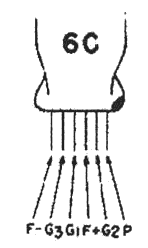
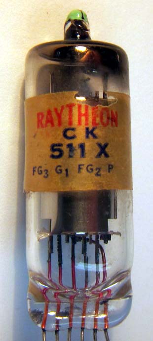
Fellow Radiophiles: Tube Collector magazine covers very unusual tube topics. One such topic was the Reentrant Pentode Amplifier, which TC editor Ludwell Sibley included in his article "Robert Adler and Tubes" August 2007 p2-p4. Sibley writes in his TC article: "...Reflecting Zenith's corporate position in inexpensive hearing aids, in 1946 he published details of a subminiature "reentrant" pentode amplifier tube. Operating as two triodes in cascade, it gave a gain of 250-500 with 45-Volt plate supply [1]. The first grid was the input. The second grid served as the plate of a triode, while the third grid acted as the grid of the second triode. Raytheon commercialized it as the CK511X, although it never gained popularity. Zenith's hearing aids used regular subminiature tubes, and ordinary Raytheon subminiature tubes later won out ..." [1] R. Adler, "Reentrant Pentode A-F Amplifier", Electronics, June 1946.
The CK511X is a relatively rare tube, but I was able to buy a couple from fellow tube collector Jim Cross at VacuumtubesInc This pentode is, after all, a dual control filamentary pentode that was designed to have most of it's transconductance from the control grid directed to the screen (gm1g2=180uS) instead of the plate (gm1p=12.5uS). This makes it easier to obtain a first gain from g1 to the screen grid g2, and then a second stage of gain from the suppressor grid g3 to the Plate. But there is a further complication; the suppressor grid also has non-inverting voltage gain to the screen grid g2. This gain is regenerative, but can be controlled to avoid oscillation as it might be done in a regenerative detector.
The schematic of the Reentrant Amplifier has nearly identical topology to a Transitron oscillator. The only significant difference is C2, which helps compensate the amplifier for capacitive loads. One can think of this circuit as a stilled Transitron oscillator. Note how voltage gain is inverting from the control grid g1 to the screen grid g2 with a gain of -20x and again inverting from the suppressor grid to the plate with a gain of -15x. The net gain from the control grid g1 to the plate is +300, which is non-inverting! I have been aware, for a long time, of the non-inverting voltage gain that is available in pentodes from the suppressor grid g3 to the screen grid g2, under certain bias conditions. This Reentrant Amplifier circuit demonstrated to me, for the first time, non-inverting gain from the control grid g1 to the plate. Such a surprising discovery made me very curious to find out just how the various gains within the tube behaved. For one, the voltage gain from the control grid to the plate works against the gain from the suppressor to the plate, because the suppressor input is inverted with respect to control grid. I took a series of measurements for the various pin-to-pin transconductances (transconductance = voltage at one pin controls current at another pin) and the various pin impedances using 400Hz sine-waves from an audio generator. The control grid g1 and suppressor grid g3 have essentially infinite input impedance, but the plate and screen grid g2 have very finite impedances as seen in the following schematic model. While the voltage of each of the four active pins g1, g2, g3, p has an effect on the current flow at the screen grid g2 and plate, no pins affect current flow at the control grid g1 or suppressor grid g3. The following LTspiceIV schematic shows all the small signal transconductances and impedances that I measured at the operating point of the Reentrant Amplifier circuit above, and produces a reasonable simulation result for gain at the plate and screen. This circuit, as the various transconductors show, has many feedback paths. My simple method to cut these feedback paths was to apply AC shorts to ground with a 2uF capacitor to any nodes that were not under measurement, and open C1=1000pF. For example, to measure the transconductance from the control grid g1 to the screen grid g2, noted in the schematic by the transconductor Gg1g2, I wired a 2uF capacitor from the plate to ground and opened the 1000pF cap C2 from suppressor to grid.
When measuring the two transconductances between the the plate and screen Gg2p and Gpg2, I wired 2uF AC ground shorts to g1 and g3, while I applied the 400Hz sine-wave from the generator to the plate and screen, in turn. The pin impedances for the plate and screen were measured by loading each plate separately, with a variable external resistance that cut the voltage swing in half. This value of resistance matches the impedance for the plate and screen with their load resistors. Then a simple parallel resistor calculation takes out the load resistance components. This resulted in a 560k plate resistance and a 117k screen resistance. These values are consistent with a dual control pentode that is oriented or biased for stronger screen transconductance than plate transconduductance from the control grid g1. One of several peculiar characteristics of this circuit is the -235kΩ negative output impedance measured at the output. This means that if a <+235kΩ real load is applied to the circuit it oscillates. And, oscillate, it did, when I applied this load! This is a problem for capacitive loads, which drop in impedance at higher frequencies. The 300pF capacitor at the screen reduces internal regenerative gain at higher frequencies and makes the circuit stable with capacitive loads up to 73pF. This finding made it very clear to me that this amplifier could not drive the several hundred pF of capacitance in a crystal earphone. It is then, likely, that this tube was used to drive an output stage with low input capacitance. When I was a hearing aid user for over ten years I learned, that the feedback whistle that happens sometimes, is not much louder than a door bell, so it is not painful. I can very well see a hearing aid user with this circuit, having a regeneration control that would give plenty of gain, which could be cut back in case of oscillation. (I no longer need a hearing aid, after my rusty middle ear stapes (stirrup) bone was replaced with a little metal piston) Best Regards, -Joe p.s.: The attached pdf contains a collection of curve traces taken on the Tektronix 575 curve tracer to show the large signal operation of this dual control pentode. Attachments
|


End of forum contributions about this tube
| Data Compliance | More Information |