
E1189_Prototype

|
|
|||||||||||||||||||||||||||||||||||||||
 por: Emilio Ciardiello
Fuente: E1189_Prototype: Manufacturer's Literature")
|
Entradas: 6446 Réplicas: 1
Development of GEC E1189 eight-cavity magnetron
|
|
|
Emilio Ciardiello
05.Oct.18 |
1
Foreword: magnetron devices were described since 1921 by Hull and perfected in the years by many scientists worldwide. Among the others, we remember the work of the German Erich Habann, who first devised a split-anode structure in 1922, the Japanese Okabi and Yagi in the second half of twenties, Maurice Ponte at CSF, Klaas Posthumous at Philips and Eric Megaw at GEC, who in the thirties perfected the split-anode structure, adding multiple pairs of segments. In America we remember the works of Samuel at Bell and of Kilgore at RCA. Nevetherless until 1940 magnetrons were nothing more than laboratory oddities, capable of delivering few tens of watts at their best.
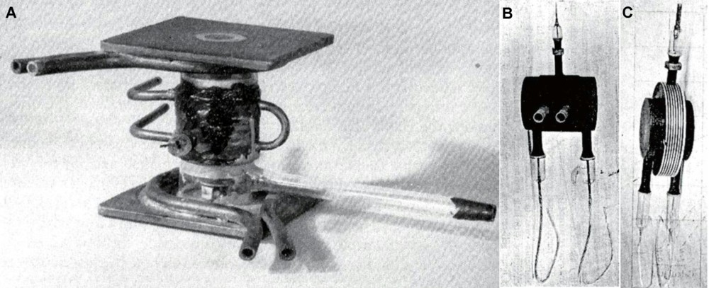
Fig. 1 - Early magnetron structures: A) CW10 was a split-anode magnetron designed by E.C.S. Megaw at GEC around the mid thirties. B) The RCA experimental A-103A with stabilizing electrodes, designed by Linder at RCA in 1936. C) RD4Ma was a Telefunken four segments CW magnetron capable of delivering about 14 W. D) A quite late GEC CV79, eight-segment interdigital magnetron. E) A GEC experimental 12-segment magnetron. The credit for the revolutionary multicavity magnetron, the one that would generate hundreds or even thousands of kilowatts within months from its introduction, goes to Boot and Randall of the group leaded by Oliphant at the Birmingham University. Instead of placing the resonators inside a glass bulb, as others had proposed before, they devised an external-anode six-cavity structure, simple to operate and in which heat could easily be eliminated directly from the anode copper block by means of any suitable radiator. We will try to reconstruct the role of E.C.S. Megaw at GEC in the developmental steps of the first operational and reproducible device, the eight-cavity E1189 often referred to as the ‘British magnetron’.
The development E1189 eight-cavity magnetron at GEC All the sources on the early story of the British multi-cavity magnetron actually talk of the six-cavity one, from the Boot and Randall prototype, first operated at Birmingham in February 1940. We know of the E1188 sealed-off design made at GEC by Megaw. It was a CW water-cooled device which required a bulky electromagnet to operate. Soon later Magaw designed two low-profile air-cooled variants, under the developmental code E1189, both suitable to be fitted into the 38 mm air-gap of a 6 lbs magnet. Originally the design had started with a spiral-wound thoriated-tungsten filamentary cathode. In the meanwhile, in May 1940, Maurice Ponte of CSF brought to Megaw two samples of the M-16 magnetron fitted with oxide-coated cathode, already tested in Paris under pulse conditions with encouraging results. Megaw decided to build a second prototype, recalculated to accommodate an indirectly heated cathode, a 6 mm oxide-coated nickel cylinder.
Fig. 2 - A) The prototype assembled by Boot and Randall at Birmingham. B) The sealed-off version, made by Megaw at GEC as E1188. C) The low profile, air-cooled variant designed by Megaw as E1189. Peak power pulses in the order of 1 kW were obtained by both samples at the end of June 1940 in the magnetic field of a standard 6 lb magnet, about 1040 oersted. In a fortnight power pulses in excess of 10 kW had been reached by the No.2 at 1400 oersted, in the pole pieces of an electromagnet. The design was only partially successful. The six-cavity magnetron with oxide-coated cathode was an outstanding source of 10 cm waves at that time, but it could never operate efficiently in a magnet light enough to be used in airborne sets. Likely Megaw, thanks to his exceptional experience, realized right away that the design had to be re-calculated for eight-cavity. From those early days of July, all the available sources are silent on the eight-slot design, until it suddenly appeared about three months later, when the E1189 No.12 was X-rayed in America. Where that 8-cavity sample sprung from? Not a word even from Megaw himself. Bowen wrote that on 7 August he attended the briefing on the magnetron construction. Soon later he was allowed to select the best sample out of a batch of E1189 units, tested by Megaw himself. He was certainly briefed on the six-cavity design, since he was not aware of eight-cavity variants until 7 October, after that his sample was X-rayed at Bell. Bowen tells of his phone call to Megaw ‘At first he was vague, and disbelieving - he was obviously as puzzled as I was.’. Then Bowen tells what he was led to believe, that is the No.12 sample was just an odd experimental unit, built in the same batch of the six-cavity ones and that just by chance had operated on the test bench better than the others. This can not be true. Fisk in his article writes that the magnetron was operated at Bell in a field of about 1100 gauss, giving pulses in excess of 15 kW. We know that the six-cavity type at 1100 gauss would have generated no more than one or two kilowatts before arcing. The experiment at Bell was then arranged with the right parameters for the eight-slot. Somewhere, likely on the test label of that unit, operating values were correctly indicated. What really happened before Bowen left GEC with his precious luggage? First of all we should consider the historic background of the days preceeding the Tizard Mission, also observing the close relation between some key dates of that mission and the development of the magnetron at GEC. Critical processes, as the gold sealing, were necessay to build the magnetron. Percy Spencer, who examined the E1198 No.12 at Raytheon, would have written ‘The technique of making these tubes, as described to us, was awkward and impractical’. The British had correctly estimated that their industry would not be able to produce the magnetron in the quantities required by military. We know that through 1941 both GEC and BTH built about 2000 units of NT98s, while Raytheon alone would have produced some 2600 magnetrons a day. On 8 July, few days that after the successful tests on the second E1189 sample, Lord Lothian, British ambassador in Washington, submited a direct appeal to Roosevelt: ‘The British Government have informed me ... that they would greatly appreciate an immediate and general interchange of secret technical information with the United States, particularly in the ultra short wave radio field. ...’. London was ready to send a small group of British military officers and civilian scientists to the United States ‘to give you the full details of any equipment or devices in which you are interested without in any way pressing you beforehand to give specific undertakings on your side'. The appeal concluded ‘for our part, we are probably more anxious to be permitted to employ the full resources of the radio industry in this country [the United States] with a view to obtaining the greatest power possible for the emission of ultra short waves than anything else.’ On 11 July Roosevelt accepted the British proposal. Likely the encouraging tests on six-cavity E1189 had given the green light to the mission that Tizard was planning for a long time. From the acceptance of the British proposal, everything had to be carefully prepared to send a working sample of the cavity magnetron to America. It was the most valuable secret that the British could offer to gain unconditional help of America. Furthermore it had to be reproduced in volume by American industries for any future British needs. In short it was the very purpose of the mission itself The story told so far does not help to understand where the eight-slot design came from. The recent accidental finding of an E1189 prototype, coming from a British Marconi warehouse and probably shelved since the war as an '8C UK magnetron', sheds new light on what really happened at GEC in the days before August 6.
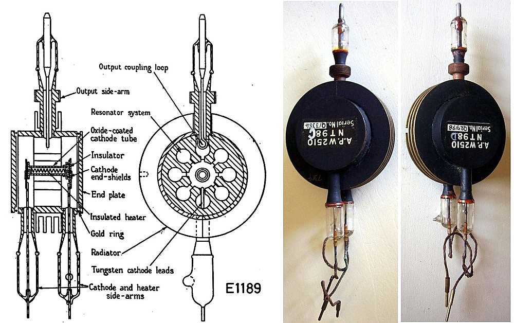
Fig. 3 - E1189 eight-slot prototype recently found. Believed to be the very early of the four samples listed by Megaw in his secret report and built at GEC in the Summer 1940. First operated around 30 July. Examining the E1189 prototype and carefully relating today the available documents of those days, the whole story becomes clear. It tells of a true miracle performed by Megaw and his team, designing the new eight-slot magnetron and then building, testing and characterizing a couple of laboratory prototypes, while assembling two complete units, all in about a couple of weeks. Megaw in his internal report on developmental magnetrons, dated 11 October, lists four units made of E1189, 8-segment type, 1050 gauss. He writes that three were still good after respectively 20, 30 and 60 hours of operation. The fourth unit worked for 210 hours, until opening of its heater. Official story tells that the E1189 No.12 was the very first eight-slot experimental magnetron made at GEC, hence these samples were hastily assumed as built sometime later for unknown reasons. Actually Megaw in his 1946 paper writes of two sealed-off samples, No.12 and 13, performance curves being reported for the last one.
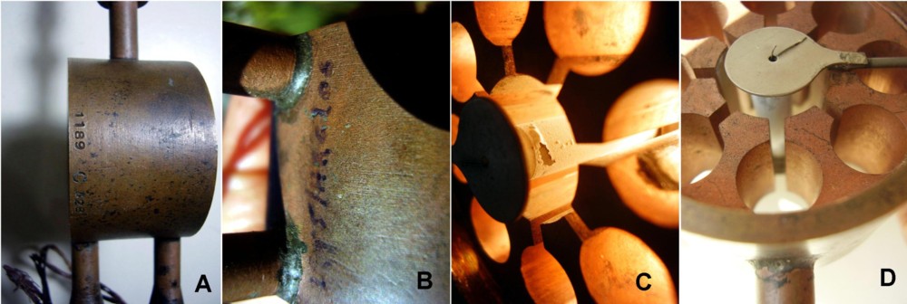
Fig. 4 - Samples of E1189 built at the date of 11 October 1940, from the Megaw’s secret internal report. Coming to our E1189 prototype, we observe that it does not have the usual finish, finned radiator, black paint and gold-sealed caps, as it was assembled in a hurry. The GEC experimental code 1189 C 328 is punched on the copper anode. There are still traces of sealing grease on the inside edge of anode block, as the unit was powered while continuously pumped. It also shows a partially faded marker writing, where the characters ‘210HR’ are still visible. Cathode oxide shows signs of heavy usage and one of the heater ends is broken near to the welding to the corresponding end baffle. Few doubts it is exactly the fourth eight-slot E1189 listed by Megaw, the one with heater open after 210 hours.
Fig. 5 - Close-up views of the E1189 prototype. A) The code 1189 C 328 is punched on the anode block. C could indicate the third revision, after the six-slot designs with tungsten filament and with oxide-coated cathode. B) In the marker writing on the side characters ‘HR210’ are still well visible. C) The oxide layer is partially swollen and detached, as caused by overheating or internal arcing. D) One of the heater ends is broken just at the edge of the end baffle. Now let us go back to the parallel stories as told by Megaw himself, by Bowen and by Sir Paterson - director of the GEC Research Laboratories - in his diary. New samples had to be made since, according to Megaw, the E1189 No.2 had been stressed up to arcing during tests. By the way the sample No.1 had been superseded by the No. 2, ending its life into the experimental microwave set installed at GEC. The sample No.2, after the test sessions, was delivered to TRE at Worth Matravers on 19 July. The Paterson’s diary reports that in the CVD meeting on 17 July the discussion dealt with a new ‘air-cooled low field magnetron’, obviously the eight-slot one, followed by ‘General demand for specimens’. Assuming that a small batch of magnetrons had to be built for the mission and for further experiments by military, its planning was likely discussed in that meeting. Eight-slot magnetron would be desirable if ready; in the meanwhile, all the programs had to go on with the already characterized six-slot type. Consequently the decision was taken of building a batch of the six-cavity E1189 for the most urgent needs, including the sample to be given to the Tizard Mission, while trying the venture with the 8-cavity variant proposed by Megaw. Whichever the sample that Bowen was to bring to America it had to be built in volume. Then the plan of Megaw looks obvious. He started building eight six-cavity units, at the same time launching a rush production of four anode blocks, redesigned to eight-cavity, with their matching cathode subassemblies. Two samples were partially assembled in a hurry, no radiator, no sealed end caps, operated continuously pumped on the bench as soon as ready. In the meanwhile, the other two units were completely assembled and serialized as E1189 No.12 and No.13. On that 6 August described by Paterson, the eight-slot designs review, still experimental until that morning, was officially approved to replace the six-slot type by ‘the crowd of visitors including Oliphant, Randall and Ellis’. Looking at the time of operation of the three good units - 20, 30 and 60 hours - we must assume that tests were interrupted all together at a given time. Likely they were kept running for some 10 hours per day and their tests were all interrupted after the approval of Oliphant, Randall and Ellis, towards the end of August 6. Should this assumption be true, we can conclude that three units started oscillating approximately on 5, 4 and 1 August, respectively. No doubts then that the last two units, those operated 30 and 20 hours, were serialized as E1189 No 12, brought to America by Bowen, and No. 13, used by Megaw himself. The fourth sample, on which the life test was later performed until opening of the heater, certainly was the first unit to operate while continuously pumped. We can assume that it started oscillating on July 30 or 31 at worst, so giving Megaw the full confidence in the design, while other units were in progress to be sealed. After the meeting of August 6, only Megaw was aware that the sample No.12 just approved was built to the latest design review, still to be filed. Other GEC employees had access to production documents of the six-slot E1189. Likely on August 7 Megaw was too relaxed to think warning of the change his employees and the same Bowen. Due to a minor lapse, on 7 August Bowen was briefed on the six-slot magnetron and later, on 11 August, he was given blueprints and production details of the six-slot design with the sample of the latest eight-slot E1189. Here a table with the most significant steps.
Click on the image to link to the enlarged PDF table The recent finding of the E1189 prototype, together with Megaw’s internal report, his 1946 paper on the magnetron development and the diary of Sir Paterson contributed to clarify the story of the British eight-cavity magnetron development. It was not the result of mistakes, confusion and lucky coincidences. On the contrary, as with other British achievements, it was the result of carefully planned and coordinated work in charge of a brilliant person, Megaw, and his team. They succeeded in a true miracle, designing, building, testing and fully characterizing the new magnetron in a couple of weeks or so, while manufacturing a backup batch of the previous type. Soon we will see the huge impact that the GEC E1189 design will have in England, in America and soon later even in the rest of the world and in the everyday life of us all. Certainly this reconstruction does not explain everything. Quite puzzling was the presence of the lateral copper tube. Mr. Yves Blanchard, co-author of the IEEE paper ‘The cavity magnetron: not just a British invention’ suggested the idea that it could be used to introduce measuring probes into the corresponding cavity. Sure it is plausible, nevertheless I personally came to the belief that the copper tube, which is the same in shape and size as the two that feed the heater, is what remains of a peephole, a glass window purposedly installed to measure the temperature of the cathode by pyrometric methods. This belief derives from a careful reading of the paper written by Megaw himself in 1946, 'The high power pulsed magnetron: a review of early developments' (*4). Back bombardment of the cathode in high frequency power tubes was a phenomenon known in GEC since the early 1930s. Megaw was certainly a very expert person but no one could have any previous experience on tubes capable of generating ten kilowatts at 10 cm and, what was even worse, on high-power tubes using oxide-coated cathodes. We must underline that the only existing magnetron with similar characteristics, the six-cavity E1189 No. 2, had been operated for the first time by Megaw himself just a couple of weeks before or so. Due to its all-metal construction, Megaw had only been able to approximately estimate the cathode temperature increase due to back bombardment by the indirect resistance variation of the heater. This technique provided very accurate results for filamentary cathodes, but it was grossly inadequate in our case. The oxide and the interface layers could be easily damaged by overtemperature due to back bombardment, up to the peel-off of the oxide. By the way the eight-cavity design had different geometries, with cathode diameter increased from 4.5 to 10 mm: any previous observation on the No.2 was then not applicable to the new device. Here the Megaw’s own words referred to the No.2 test: ‘The output at 6 microsec was independent of heater voltage down to zero with the oxide-coated sample, and its success was regarded as completely established. An early mercury-vapour triode (E1191) modulator was used. The wavelength was near 9,8cm for both valves. Within a fortnight peak outputs of 10 kW had been measured in a water load with an input of about 10 kV, 8 A, 30 microsec, 50 pulses/sec; the field of about 1400 oersteds was provided by an electromagnet. With higher inputs, powers estimated at over 15 kW were obtained, but with the large pulse length used persistent flash arcs occurred at this output. The cathode bombardment power was estimated by heater resistance change in No. 2 (the one with oxide-coated cathode) at 5-10% of the mean input, increasing appreciably as the load coupling was reduced.’ Therefore Megaw had to build this laboratory specimen, without the finned radiator and with the peephole looking at the cathode surface, in order to fully characterize his design. The close-up view of the cathode surface visible in fig. 5 testifies how roughly he stressed the tube, even sometimes beyond its limits, in any predictable condition of input pulses and of load. That little copper tube was essential to give Megaw the full confidence with the new design over the full range of expected operating conditions. This detail confirms how accurate was the Megaw’s design, well far from the lucky experiment painted by Bowen. Last edited on May 14, 2020 by Emilio Ciardiello References and bibliography
All the tubes photographed in color are from the collection ase-museoedelpro |
|
Emilio Ciardiello
16.Oct.18 |
2
Part II, early evolutions of the design in 1941 We know that the early eight-cavity samples of E1189 were ready by August 1940. Unfortunately the magnetron was just one of the components needed to build a microwave radar. Other new components had to be designed and tested, as they were, in 1940. Among the others devised in UK we remember the ‘Sutton’ reflex klystron, the silicon diode mixer and suitable switches for the pulse modulator. TR switches appeared quite late in 1941, since early microwave radar sets used two separate antennas for transmitter and receiver. The British development The preliminary specs for the Naval radar Type 271 and the Army radar GL3 were defined around November 1940. Copy of the GL3 preliminary specs was also submitted to Canadian REL for local productions based upon procurements of American components. We know that the first experimental radar Type 271 was installed in March 1941 aboard of the HMS Orchis. The radar became operational by July 1941 and the magnetron, simplified in its radiator, was standardized as NT98. This magnetron was manufactured by both GEC and BTH. We know that within the end of 1941 about 2000 units had been built. Quite soon sealed-off units were selected according to their frequency of oscillation, grouped into four variants A to D. Damaged units had to be returned to repair shops for rebuilding, if feasible, or to recovery precious and strategic metals, gold, copper, nickel and tungsten. According to Megaw, the development of high-power magnetrons started right after the delivery of E1189 early samples. He reports that a sample of a 100 kW magnetron was nearly to completion at the date of 11 October 1940. It originated the CV41, manufactured in small quantities in 1941. The frequency variant E1198, operating at 9.1 cm, was ready by September 1940 for airborne applications. It was later approved as CV38.
Fig. 2.1 - Draft of the eight-cavity E1189 magnetron. Right, two frequency selections, C and D, of NT98. In July 1941 J. Sayers at Birmingham University devised the strapping technique to prevent moding of magnetrons. Before, at high power levels, mode jumping resulted in low efficiency and could cause the destruction of the cathode. Strapping forced the magnetron to oscillate with phase shift of 180 degrees between adjacent cavities, resulting in stable and efficient operation which opened the way to virtually unlimited increase of power. CV56 and CV64 were the early strapped magnetrons, available by the late 1941. CV56, replacing the NT98, was rated for 80 to 100 kW output pulses with about 40 % efficiency. It was followed by the more powerful CV76, capable of generating 450 kW pulses. CV64 was developed by BTH to replace CV38. In its first airborne applications its output pulse power was limited to about 40 kW, but it operated at 160 kW pulse power when a more powerful modulator based upon the new CV125 trigatron was available.
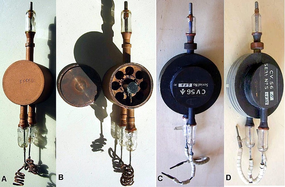
Fig. 2.2 - A) and B), two images of an experimental strapped magnetron, likely built by the Sayers group at Birmingham in the summer 1941. C) An early sample of CV56 strapped magnetron, likely build shortly after the experimentation at Birmingham and before the frequency selections was decided. D) A sample of CV56A, one of the four frequency selections. Note the suffix and the serial number added manually, actions likely performed at the completion of the test procedures.
Developments in America and in countries of Commonwealth The E1189 No.12, brought to America by the Tizard Mission, originated a small batch of test and qualification samples, exact copies of the British prototype. From November 1940 Western Electric delivered some 60 units with the developmental code D-160052, part of which went to the MIT Radiation Laboratory for experimentation. This developmental magnetron was followed in 1941 by two separate productions from sister companies: in Canada the Northern Electric built for REL the 3D, while in Australia the Standard Telephone and Cables built the NTA98.
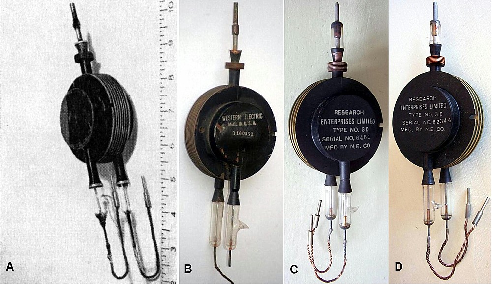
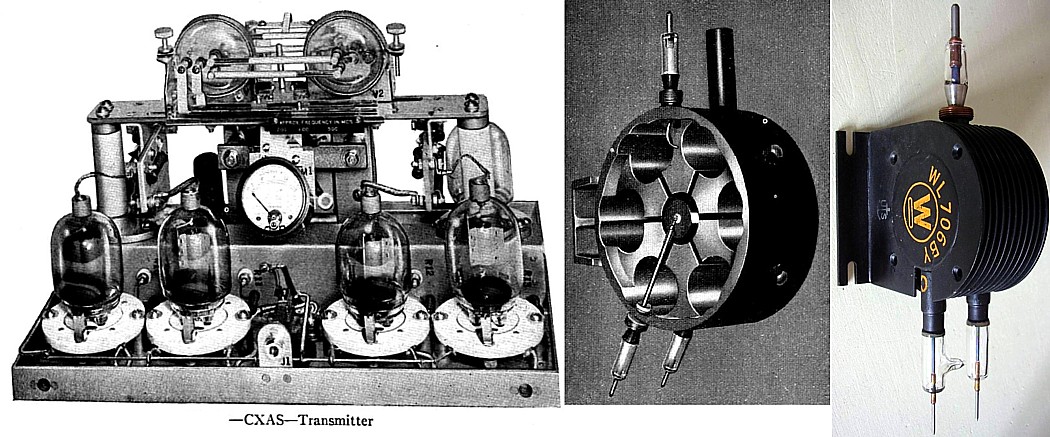
Fig. 2.3 - A) The E1189 No. 12 brought to America by the Tizard Mission. Today on display at Canada Science and Technology Museum, Ottawa. B) The Western Electric D-160052 was the Bell reproduction of the above sample. The unit S/N 56 coming from the closure of MIT Radiation Laboratory was in the collection of the late Jerry Vaniceck. C) REL 3D, made by the Canadian Northern Electric, was equivalent to the British NT98. Northern Electric was a Bell owned company. D) REL 3C was the equivalent of the British frequency variant made for Air Ministry, the E1198 approved as CV38. In America the first magnetron family designed at Western Electric in 1941, the 700 A to D, considerably departed from the British E1189. It was a family of six-cavity low-frequency magnetrons, which included four frequency variants around 700 MHz. This because Bell at the time of the Tizard Mission was working at its Whippany radio laboratory to the development of the fire-control radar CXAS for the Navy, operating between 500 and 700 MHz. When in October 1940 Bell arranged the test of the British E1189 magnetron, their transmitter, based upon their best doorknob triodes, generated a kilowatt or so in output. They saw the immediate opportunity for switching to the new device. The first magnetron designed at Western Electric was readily integrated in the transmitter of CXAS, raising output pulses to 40 kW.
Fig. 2.4 - Left, the transmitter of the CXAS radar. The RF oscillator is on the top. Center, the 700A magnetron which gave a forty fold increase of the pulse power. Right, 706 was the first 10 cm magnetron designed by Western Electric. With respect to the British E1189, the WE design had a more efficient finned radiator and side fixing brackets. It was rated for about 25 kW output pulses. The sample in the photo is a later strapped unit, rated for output pulses exceeding 200 kW. We will see elsewhere subsequent developments of the magnetron E1189 in England, in America and from 1943 also in Germany.
References:
|


Fin de las contribuciones al foro de válvula
| Cumplimiento de datos | Más información |