Reinartz Moduloscope Homebrew - who builds one?
Reinartz Moduloscope Homebrew - who builds one?

It is a fact that we should attract young persons to our hobby fro having followers who are interested also in our collection when we pass away. It is a fact that at least in Europe young persons are not interested in radios because they get them in superb quality for nearly no money and AM stations are missing for building simple radios and detectors.
And it is a fact that interest as such is part of a character but may be perhaps teased with spectacular experiments with radio waves. "Interest as such" is the opener for a good and happy career since one does not a job but a vocation!
This all is the reason why I switched from samall radio projects for young people to other techniques for demonstration of interesting characteristics of electricity and radio waves, such as high voltage (Wimshurst or Bonetti or others), Geissler or Crook tube experiments, gentle electrifying sets, sets for tickeling persons (HF-nervstimulator, "med. Reizstromgerät"), very early radio waves or HF-buzzer, Tesla experiments, early transmitter / receptor, mysterious music (theremin), etc. For the latter we know more complicated gear - the too complicated Trautonium.
Even the unipolar machine of Barlow (Barlow's wheel or a homopolar or unipolar generator) can be of interest. Later some radio experiments and views with a simple oscilloscope or with just a tube for it may be possible.
Very near to radio and simple to build - with radio parts - is the homebrew Reinartz Moduloscope. Sometimes it is also called vacuum tube Tesla coil. Philip Colston, Setauket, USA, was so kind to send me an OCR scan from "Modern Mechanics" of 1932 of the article how to build an other version. I can just use his scan and will add some pictures from the journal.
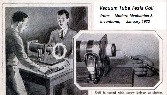
Vacuum Tube Tesla Coil Does Fascinating Stunts
from Modern Mechanics & Inventions, January 1932, page 92 - 94 and 140/141.
Light bulbs and spinning wires which glow with weird effects, cigarettes which light mysteriously—these are a few of the stunts you can do with this vacuum tube Tesla coil.

You find all five pictures large (1400 pixels width) on the model page.
See also other builds there.
THE older types of Tesla coils, calling for a high tension transformer and spark gap for excitation, were undoubtedly interesting and instructive, but the one shown in the accompanying photographs and sketches will prove much less expensive to construct and yet will provide plenty of sure fire fun and spectacular results. It makes use of many radio parts and therefore should prove very inexpensive to construct by those readers possessing a stock of spare radio “junk.” It is simply a matter of plugging in to the 110-volt electric light line to carry on an almost endless number of interesting and instructive experiments in high frequency currents.
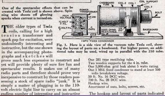
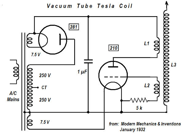
You will need the following parts:
A baseboard 18 in. long by 10 in. wide.
Cardboard tube 8 in. long, 4 in. diameter.
Cardboard tube 11 in. long, 2-1/2 in. diameter.
Two radio UX sockets.
Transformer giving about 500 volts and provided with two 7-1/2-volt filament windings.
One 210 type radio tube.
One 281 type rectifying tube.
Two wooden supports for the 4 In. tube.
One 5,000-ohm grid leak about 5 watts rating.
One 1 Mfd. fixed condenser to stand at least 500 volts breakdown voltage.
50 ft. No. 16 DCC wire.
700 ft. No. 28 DCC wire. Hookup wire.
Assortment of nuts, bolts, screws, etc.

The hookup and layout of parts indicated in Fig. 2 should be followed to the letter to insure best results. Place the transformer at the left end of the baseboard near the rear. Then mount one of the sockets in front of it for the rectifying tube (281). To the right of the tube mount the fixed condenser. Mount the two coil supports to the right of the transformer. Then in front of this coil mount the remaining socket for the 210 oscillating tube.
Now comes the winding of the coils. First wind those called Coil 1 and Coil 2 on the 4-inch tube. These consist of 20 turns each of No. 16 DCC wire. Note the dimensions and spacings on the diagram (Fig. 2). Wind closely and tight and space them 1-1/4 inches apart. Wind in the same direction and secure the ends by any manner at hand. Wind in the same direction as the two former coils and secure each end to a bolt, the right hand one projecting out two or three inches from the end.
Mount the 4-inch coil in the supports as shown. Now slip the 800-turn coil (Coil 3) inside the larger tube and by means of blocking or little angle pieces, support it in the center of the large tube equidistant from all sides as illustrated in Fig 4. Solder all connections not secured by connectors or binding posts and make all leads as short as possible. Hookup wire can be either bare copper wire covered with spaghetti, or any type so long as it is well insulated and about No. 18 gauge.

Start with Coil 1. Connect the outside lead to one side of the fixed condenser and to one side of the filament winding used to light the rectifying (281) tube. The inside lead of Coil 1 then connects directly to the plate terminal on the 210 tube socket. Now connect the inside lead of Coil 2 to the grid binding post on the 210 tube socket and connect the outside lead to one end of the grid leak resistor. Connect the other side of the grid leak to the inside end of Coil 3 (next to the transformer), to the iron core of transformer to filament post of 210 tube, to one side of the high voltage winding on the transformer and remaining side of fixed condenser. The remaining side of the high power winding is then connected direct to the plate of the 281 tube. Each filament winding is then connected to the filament terminals of the two tube sockets. This completes the wiring. The transformer primary should of course be provided with a cord and plug.
To test first plug in the transformer. This will light the tube filaments. Then, to see if the high voltage is energizing the Tesla coil, run a screwdriver or other metal tool up and along the bolt at the protruding end of Coil 3, as demonstrated in the photo on page 92. It should draw sparks as it passes over the threads and will prove it is working. If no show of energy occurs go over the wiring thoroughly (first pulling the plug) and look for disconnected wires or poorly soldered joints. When properly hooked up it will surely work and you are then ready for a number of highly fascinating experiments.
With your Tesla coil operating properly you are ready for some of the most weird and interesting experiments imaginable. First, do not fear a shock. Slight burns may result if taken on the bare flesh but if one holds a metallic object in the hands no sensation is noticeable. Therefore, there is no danger.
First let’s see what can be done about drawing a spark from the bolt on Coil 3. Hold a metal tool in the hand and gradually bring it near the bolt. When the breakdown distance is reached sparks will jump between the two metals similar to lightning. Too great a voltage must not be used, but any voltage from 350 up to about 750 volts is perfectly safe.
Now let’s try a little experiment with an electric light bulb. If you can get hold of a bum one so much the better. First fasten a small metal ball to the end of the bolt. Then, holding a 15 or 20-watt bulb by the glass, bring the metal ferrule near the bolt. As it approaches it will commence to glow and change colors according to the gas in the bulb and the power of the coil. Get a bulb in the “Five and Ten” marked “made in Japan” if you want to see some fascinating effects.
Here is another fascinating demonstration. Fasten a very fine, stiff wire to the bolt and bend it up and outward in a wide curve as illustrated in Fig. 5 (besides in fig. 4). Plug in the coil and watch the result in a darkened room. Varying the output voltage will change the glow around the wire and at the very end will be seen a very concentrated discharge of fire.
Here is one of the most spectacular stunts of all. It is a rotor spinning from the high frequency oscillations and emitting a changing corona discharge ever fascinating and beautiful. Bend a piece of fine wire such as No. 22 or 24 into a wide S as shown in Fig. 5. Slip this over a piece of stiff wire fastened to the end of the bolt horizontally. The wire must rotate freely and be free from kinks or corners. Start the coil and watch the S wire spin. It will rotate at terrific speed well up into several thousands of R.P.M. All around the circle will be seen an even number of brush discharges and the peculiar thing is that they will always be an even number.
Here is a way to mystify the crowd. Hold a match head near the bolt. No effect is noticed. Then wet the head so it is soaking. Hold it near the bolt again and it lights! The dry head was non-conductive but the wet head acted as a metallic conductor and soon ignited from the spark produced. Done with the bolt and coil hid behind a thin partition makes the trick doubly mysterious.

As the user becomes accustomed to the action of his Tesla coil he will discover many more interesting and instructive uses for it. Common things can be utilized to produce many weird results and spectators will never tire of watching the effects of its action. As before stated, there is not the least danger in its effects. But, don’t get careless with the direct output of the transformer itself. The current produced is at a much lower frequency (60 cycles) and 500 volts or more at this frequency will give quite a kick if taken through the body.
To thank the Author because you find the post helpful or well done.
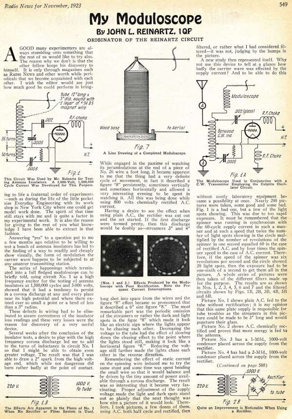
Some details about the build in QST 1923
Philip Colston was so kind to send me some details of the build shown in QST June, 1923 which I put in big to the model page and here in the forum format of 600 (last = 570) pixels width. Philip informed me that there is also an article in the October 1924 issue of the French magazine La Science et la Vie: Le Curieux Modulascope Reinartz. The pictures are from the 1923 QST article.


To thank the Author because you find the post helpful or well done.
Reinartz Moduloscope in "Radio News" November 1923
Guest Philip Colston sent me now also the scan of the article "My Moduloscope" by John L. Reinartz, 1QP, the originator of the Reinartz Circuit. It is entirely built with cheap radio parts and the first build was used by Mr. Reinartz for testing antenna insulators at 1'500'000 cycles and 5000 volts. With the second build he wanted to obtain even greater voltage. The result was that he was able to draw a 2" spark from th high voltage end. In contrast to other sparks made with high voltage this is not danguerous for us, but can burn rather badly at the point of contact. Therefore one uses a metallic tool so that the entrance into the body will not be a point but an area - and nothing is felt.
The secondary Tesla coil would only be dangerous if a capacitor would be used at this secundary. You find the much bigger scans again on the model page. I tried here to reduce size in a way that it is just readable, but the pictures are still clear to grasp the build.
To thank the Author because you find the post helpful or well done.
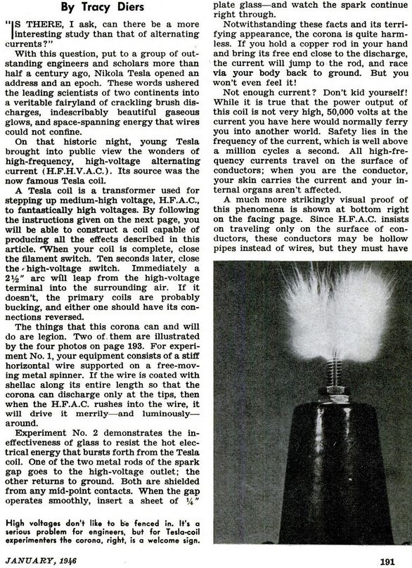
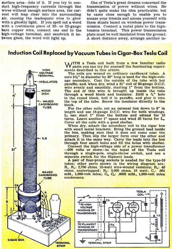
Ordinary Tesla Coils are easy to build
I wuold like to remind that the purpose of the Reinartz Moduloscope is quite a different to a simple Tube Tesla Coil, which was presented in the journal Popular Science, January 1946, page 191 to 192.
I hoped to get some members finding out how simple and less dangerous a build from ordinary receiver parts can be made, because the opposite, a huge Tesla Coil has been made many tmes - with voltages far above of a million volts. The tuned Reinartz Modulascope (Moduloscope), shown by S. Kruse (see above) shows the purpose of a "measuring instrument". I would like to see this realised by one of our members, trying a most simple build with a normal mains radio transformer and radio tubes - and then power reduced as much as possible so that the "spinner" just works stadily.
I think it can be done easily safe if only the upper part of the tesla coil including "spinner" is accessible to other persons.
I still show you the build of a simple tube tesla coil, which can also be made save!
To thank the Author because you find the post helpful or well done.
My homebrew Moduloscope

The question in November 2015 was: Who builds a Reinartz Moduloscope?
Having read the proposals in post 1 and 2 I thought, yes that would be something different! Thus, 14 day’s ago I started a new project “My own Moduloscope”. I was charmed by the concept and the vintage look as depicted in post 1 dated in 1932.
Easily to build no special parts, except for the USA tubes 210 and 281 which I don’t have in my junk boxes…
I thought by myself the Telefunken 15W power triode RS241 should be ok and for the rectifier an RGN1404 will perform perfectly as well.
This is the original circuitry
My first attempt was rather disappointing, nothing happened!
We know, the whole thing is in fact a CW-Oscillator coupled to a resonant transformer. Therefore, the primary circuit should be in resonance with the secondary one.
With the help of a Grid-Dip Meter the HV-Coil L3 (with its own capacity) the measured frequency is around 900 kHz. Because of the much less windings of L1 the resonant frequency was in the region of 2600 kHz. An obvious mismatch!
To tackle this problem, I decided to add a condensor C1 in parallel to L1. Furthermore, a variable condensor C2 will give some additional fine tuning too. A change of the already fixed windings of L1 and L2 was too troublesome, honestly spoken…
With the mentioned alterations first signs of live were noticed!
Not only sparks at the end of the HV-Coil but unfortunately also inside the tube! It turned out that the RS241 was not capable to cope with the high peak voltages at the anode. This is because of the insufficient internal insolation of the wire leading to the plate.
Having said this, a triode with an anode outlet at the top would be the solution. Again, nothing of that kind was found in my “stock”. So, let’s try my Telefunken pentodes RES 664d or RES 1664d. Why not?
It was a good move. Suddenly I got results. Thanks Heaven, it works!


Above we see the final approach of my Moduloscope. On second thought I changed the old rare and valuable tube against a modern, easily to get type from tv-sets.
The only special part is the already mentioned variable condenser C2. We can’t use the normal ones from a wireless. The distance between the segments must be at least 1.5mm. Radio-Amateurs will have them…
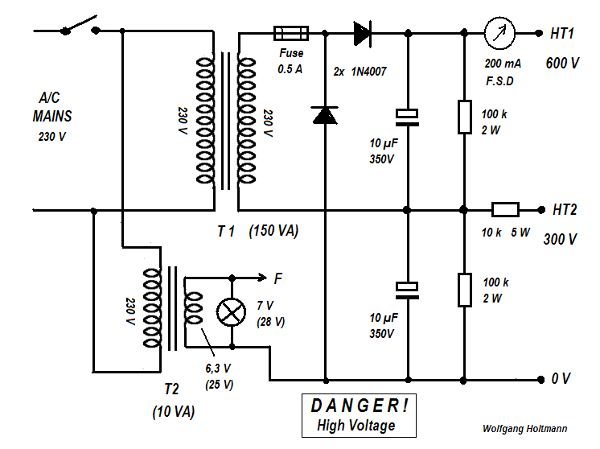
Also in the power supply section we see semiconductor rectifiers arranged as a Delon Voltage Doubler. With this trick a common 1:1 power transformer with two separate windings can be used. Of course, an additional transformer T2 for the filament is now necessary and must match with the tube.
Important: SAFETY FIRST !
When we look at the examples given, deadly anode voltages (above 500V) are used! This project is certainly not to recommend for young and less experienced people! Look at the bare and free accessible connection points on all three proposals!
In my version a plywood bracket prevents direct contact with dangerous voltages. I intend to do the same with the other sides of the Moduloscope leaving only the harmless end of the HV-Coil open. Further on this subject, see post 4 by Mr. Erb two days ago.
Some photo’s

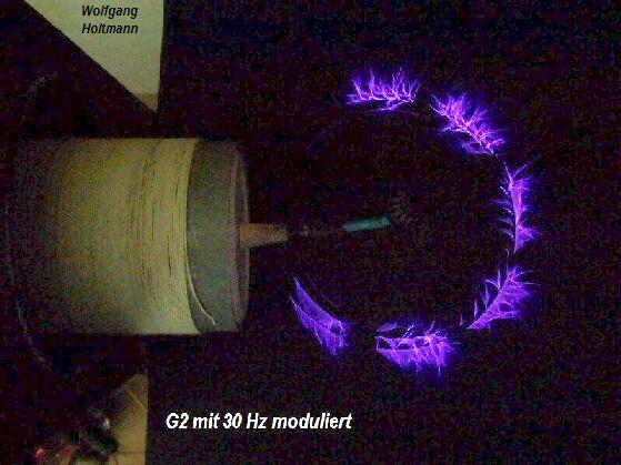
A close-up picture of the “spinning S-wire”

The reason why this thin wire will rotate can be explained this way: the exhausting plasma gases at the ends form “rocket engines” giving little thrust to move in one direction.

This picture shows the spinner in a different position.
By the way, to let the whole circle glow the distance to the coil end must be enlarged! This will produce a more evenly static field around the spinner.
Here the explanation why Reinartz called his apparatus “Moduloscope”:
We see interruptions in the normally closed circle. He did this by feeding the oscillator with A/C, or a pulsed anode voltage derived from the power supply. He had the choice of 60 Hz or 120 Hz. I took it a step further by inserting a small transformer T3 in the screengrid circuitry in order to have the liberty in different sources of modulation. This can be an audio generator producing sine waves in the range of 10 to approx. 150 Hz.
Belief it or not, with the spinner removed one can really hear the sound of music! Simply connect an audio amplifier to the primary of T3. In fact, we created a so called Plasma-Speaker.
No, it’s not Hi-Fi …
Edit 23.6.16 20:50, PVC-Pipediameters corrected.
To thank the Author because you find the post helpful or well done.
Questions: RFI and safety?
I wonder how much radio interference it generates?
It looks amazing.
I'd been wondering about making one using a SMPSU 900V FET and fitting iinside a scrap microwave oven case. Safety and RFI screening. Perhaps replace door with a finer RF screen, made from a €2 frying pan splatter guard, more transparent.
To thank the Author because you find the post helpful or well done.
--
Dear Michael
With regard to the RFI issue I made two “investigations”.
1. Because the basic frequency of my Moduloscope is nearly 900 kHz (with some NBFM) the range of interference in the neighbourhood was tested with my car-radio. With the wheel of fun still spinning I drove down the lane and after 150m the noise vanished. In other words, in case someone (like me) in the block is interested in MW-Reception, it will be quite bothersome!
2. A more detailed verdict can be obtained with my Spectrum Analyzer. In the frequency range from 900 kHz to 500 MHz (= max. for the HAMEG HM8028) I noticed unwanted signals all over the place….
The maximum is in the range between 200 and 300 MHz. My explanation is: The S-wire with its dimension acts like a small antennae and favour those frequencies. Although I tried my best, it was not possible to take a clear photo. You have to take my word for it…
A closer look reveals, one can see additional sparks at the centre of spinner. This is due to the unreliable contact with the rod, yet another source of distortions.
Talking about safety:
Read this:
"But, don’t get careless with the direct output of the transformer itself. The current produced is at a much lower frequency (60 cycles) and 500 volts or more at this frequency will give quite a kick if taken through the body." (1932)
I made it already quite clear, surely we must tighten up precautions preventing direct contact with lethal voltages. A good and complete cover is advisable. Also your idea of an old scrap microwave oven case sounds not bad…
Yes, with modern semiconductors it is surely possible to generate high voltages with a low voltage (12 volt) supply. Look at the old portable b/w tv-sets. Another example are the ignition modules used in gas vehicles.
Kind regards
To thank the Author because you find the post helpful or well done.
Semiconductor version
I was thinking direct off the AC mains rectifier (and even a doubler)! Even 1000V power FETs (200W) are only a few Euro. The issue is that the high power types are in reality many parallel devices on a chip, so gate capacitance is 1000pF to 3000pF depending on power rating. However I've used TO220 80V power FETs at up to 4MHz using 12 Ohm source impedance drive. The Tesla coil can provide the isolation, and in any case I would run it in a fine wire mesh cage. I will see what the lowest gat capacitance device I have or is cheaply available.
I always fancied trying to make a plasma loudspeaker!
To thank the Author because you find the post helpful or well done.
---
Sorry Michael,
what you have in mind is not what we are looking for!
The basic idea is, how can we engage youngsters in electronics?
This can be done by attractive experiments for example, the amazing Tesla Generator.
In this thread Mr.Erb made three suggestions. All of them are not foolproof, because dangerous supply voltages are involved!
The next step
To achive the desired goal we think about something using a low voltage but high current circuitry in order to drive the secondary Tesla Coil. You are right, power FET's are a good choice...
Kind regards
To thank the Author because you find the post helpful or well done.
Young People
I suppose if it would work off a 5V phone charger that might be better. About 5W should be enough power. I will try an IRF740 or similar as I've used them at 4MHz.
Another possibility is to modify the €5 single use flash film cameras still in the shops. I've used the electronics for the flash as a capacitor tester by swapping the 300uF for 1uF and adding two x 1M Ohm resistors, a 0.1uF cap and a neon. Perhaps the rectifier can be be bypassed and the little generator (works off one AA cell, included) feed a Tesla coil. I have a spare one so I will try that with my grandson next week. They generate about 400V with no load.
I'm doing electronics with my 9 year old grandson. He's very keen and in reading comprehension is off the scale in school. He assembled a Morse code practice oscillator using a kit we got with spring connections. Then he wanted to make the radio. We only get AM MW after dark (from UK) as the sole Irish MW station is at the other end of the country and dark is too late in the summer time. So I changed the stock coil to make it work on LW and when we added an earth and giant aerial wire it did pick up the local RTE1 radio on 252KHz, though performance was too poor for BBC R4LW 198kHz. Next he learned to solder and soldered a simple two transistor oscillator with cheap 8 Ohm speaker running of 9V battery for Morse code learning using matrix board, just soldering the wires to each other. He first assembled the circuit from the Internet on proper socketed breadboard. I downloaded about four different circuits and explained it was faster than me designing one. I explained why we were using the one I chose, one resistor, one capacitor, PNP and NPN transistor and direct drive of a speaker.
The last project was an intercom from two cheap telephones, three D cells for power and scrap CAT5 cable. He has that between his bedroom and dining room at his home.
He has learned what all the parts are on the schematics and redrawn them himself. He's keen when he finishes school for the summer, next week, to come regularly. Perhaps we will try the Tesla coil, but it needs at least an RFI and electrical screen as his brother and sister are younger and what ever he makes they are keen to play with at least once.
The Electronics sets are not very good. I got three very cheap from charity shops (all complete). Perhaps there are really only two or three worth building circuits in them, with many being variations of the same. One had a mistake in the instructions and thus the circuit wouldn't work. That was useful for the grandson to see that one must learn the principles as recipes can have mistakes. They are poor on explanations.
I have a nice one transistor VHF regnerative receiver design that can tune using a straw with a piece of brass and ferrite in the coil. It does about 80MHz to 130 MHz and easily gets all the local VHF-FM and the local Shanwick Airband traffic. Probably for speed we will use a 50c LM386 or similar audio amp, though I have made one that used transistor audio amp, earphone and a single AAA cell all in a small matchbox. That's too fiddly to solder till he is older. You mark the stations on the outer of the plastic straw.
To thank the Author because you find the post helpful or well done.
So Father, so grandson !
Good morning Michael
I'm speechless...
It's amazing what you both have achieved so far!
Surely, he will become an engineer in electronics in the future.
Chapeau!
To thank the Author because you find the post helpful or well done.
 Thread closed by a moderator. But replies can be made through a moderator.