telefunken: Telefunken 5183wk Restoration
? telefunken: Telefunken 5183wk Restoration

I am restoring a Telefunken 5183wk console that was in bad shape when I got it. It was free to me on condition that I restore it and send pictures / video that they could show their Dad who is in an assisted living facility. 


The Telefunken 5183wk had been modified with a Eicor FM stereo modulator added. It also had the power switch bypassed, ac plugs added with some kind of rear speaker volume balance. All of this has been removed and power switch reconnected.
Powered up on my dim bulb tester and I was able to play music via the PU input. Very distorted and volume pot / balance control was not working. So, I proceeded with replacing all the electrolyte and paper / wax caps. Cleaned the volume pot and after several attempts with contact cleaner, oil and complete flush out with more contact cleaner and then fader lube I was able to get the frozen balance to move freely.
So now it is working and sounds better, but I still have some issues and could use some advice.
- I am getting a 60hz hum that I can hear with volume at zero and it does get louder when I turn the volume up. Does this indicate a short or bad pot? I am suspect of the volume / balance pot since it was so badly frozen. Any thoughts on what I should check? I also get slight bleed through of the radio or PU input that I can still here even with the volume at 0.
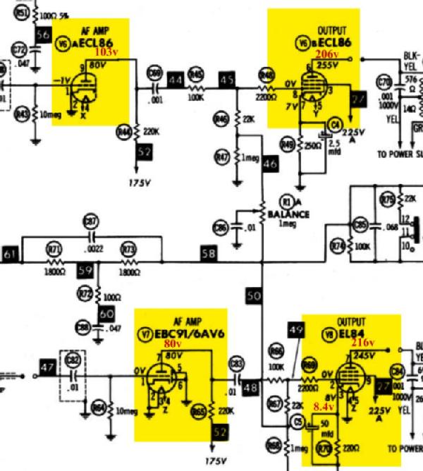
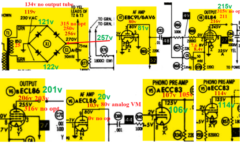
- I have checked the voltage on the tubes and have attached the marked-up schematic. Voltages are low on all but the ECL86 that should be 80v and is reading 103v. Does this indicate a bad tube?
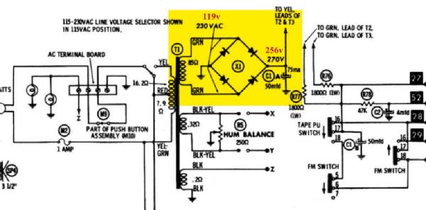
- I have replaced the selenium rectifier with a N4007 bridge and added a 100ohm 10W resister. Voltage drop is about 5v and the voltage stabilizes at about 256v vs the specified 270v. Should I go with a lower ohm resister or is this within tolerance of the rated 270v?
- The transformer is getting very hot. I am not sure what “normal” temp should be, but it seems to plateau at about 71C. Is this normal, or could this be a bad tube or a short?
- I am trying to understand how the internal speakers are configured. The system has 3 speakers (two 3 inch tweeters and one 7x10 woofer). There are 3 wires coming out of the top of the power supply / transformer block (2 white and one red), but I suspect this was not original as the wires to the speakers are red, blue, green. There is a 25uf cap between the woofer and the 2nd tweeter. Does one of the wires from the transformer block feed the first tweeter and somehow act as a crossover? Then the second provide full range with the cap used to high frequencies to the tweeter?
Sorry I know that a lot of questions. Any suggestions you have will be very much appreciated. I am trying to decide if I should buy new tubes or keep troubleshooting for a short.
Thanks
To thank the Author because you find the post helpful or well done.
telefunken: Telefunken 5183wk Restoration

Dear James,
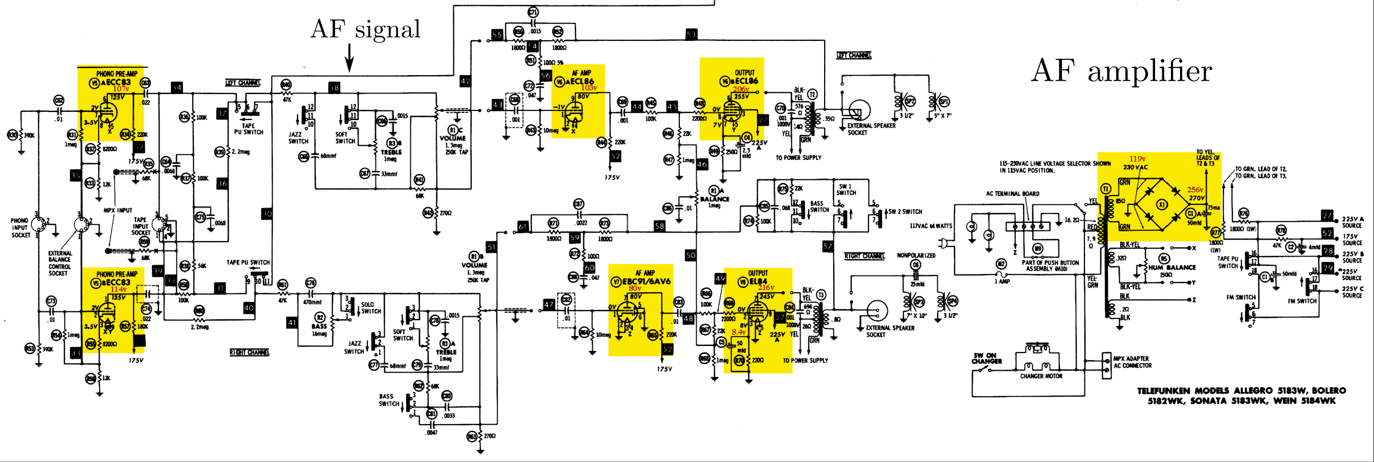
it would be very helpful if you could upload first the schematic of your receiver. You write "and have attached the marked-up schematic". But up to now, there is no schematic with the model?
Howto prepare a schematic is discused in "Schematics perfect.."
Regards,
Dietmar
To thank the Author because you find the post helpful or well done.
telefunken: Telefunken 5183wk Restoration
A few general comments while waiting for the schematic:
Are you sure that the hum is 60 Hz and not 120 Hz? The combination of a hot mains transformer, 120 Hz hum and low voltages everywhere is typical when the current consumption on the B+ voltage is too high. Possible reasons could be leaky coupling capacitors at the control grids of the output tubes or that one of the output tubes has got secondary emission from the control grid. Both of those faults will cause a positive voltage at the control grids of those tubes, and too high voltages across the cathode resistors (which often will burn out after a while).
You can check if the mains transformer is in order by disconnecting one wire to the AC side of the bridge rectifier, switching the set on without B+ voltage, wait some time and check that the transformer now doesn't become hot.
If one diode in the bridge rectifier is bad (either open, shorted or connected the wrong way around), you will get low voltages and 60 Hz hum. The mains transformer will get hot in those cases, probably even when one diode is open, due to the DC biasing of the iron core.
The reason for a high voltage on a pin of the ECL86 (i guess it is the triode anode) is commonly that this is a high impedance point, it is supplied via a resistor of some hundred kohms. If now the voltages stated in the schematic were measured with a low impedance moving coil multimeter, this node was loaded down by that multimeter causing a low reading to be noted in the schematic. I guess you're now using a modern digital multimeter with about 10 Mohm internal resistance, which doesn't load down the circuitry in the same way.
When troubleshooting hum problems that aren't clearly obvious, it is very handy to use an oscilloscope. Then you for instance can check the waveform of the hum and check its phase relationship to the voltages on the mains transformer secondary, superimposed hum on the B+ voltage etc, this will help you to conclude whether the hum is coupled via the B+ voltage or somehow directly by and AC voltage, you may see if it seems to be resistively or capacitively coupled, etc etc.
Best regards
Torbjörn Forsman
To thank the Author because you find the post helpful or well done.
telefunken: Telefunken 5183wk Restoration
Hello Dietmar,
Thanks for the fast response. Sorry, this is my first post on this form, and I am still getting familiar with how it works. I thought that I attached some links, files and pictures to my post, but now I am not seeing them. Seems the file size limitation makes it a challenge to upload the schematic with my notes and keep it readable. I included a link to my google photos that has the full schematic marked up with my voltage notes if that will help. Also attached are smaller screen captures of each tube voltage measurement so you can read it clearly. Look forward to your feedback.
Best regards, James
To thank the Author because you find the post helpful or well done.
telefunken: Telefunken 5183wk Restoration
Hi Torbjörn,
Thanks for your quick response and questions. I have attached the marked-up schematic.
It may be a 120Hz hum. I have replaced all the capacitors and double checked all solder joints. I have no tube tester, so I want to eliminate all other possibilities before I start replacing tubes.
As you suggested, I checked the transformer by disconnecting one of the wires on the AC side of the bridge rectifier. It appears the transformer is no longer getting hot (just slightly warm). In disconnecting the wires to the AC side of the bridge, I discovered that the insulation on these wires was very brittle and had exposed the wire in a few spots. I am not sure if that could have caused a short, I did not see it in contact with anything. I will address this wire insulation issue and reconnect for testing tomorrow.
I will report back with results. Let me know if you have any other suggestions.
Thanks,
James
To thank the Author because you find the post helpful or well done.
telefunken: Telefunken 5183wk Restoration
James,
I offer you help in creating a wiring diagram that meets the requirements for Radiomuseum.org.
Please send me the schematic in sufficient resolution to my email address.
From the (practically unreadable) schematic in post #6 you can guess that the radio has a pseudo-stereo output stage.
Best regards, Dietmar
To thank the Author because you find the post helpful or well done.
telefunken: Telefunken 5183wk Restoration
Hello Dietmar,
I sent and email via the link "Mail to the author" and have attached the schematic. Thanks again for you help on this!
James
To thank the Author because you find the post helpful or well done.
telefunken: Telefunken 5183wk Restoration
After removing one of the wires from the AC side of the bridge rectifier to confirm the transformer did not get hot, I moved on to making sure all the wires were properly insulated since I have noticed a crack in one of them.
I'm not sure there were any shorts, but I did go through and address all the transformer / power supply wiring to make sure there were no other breaks. Any brittle insulation was replace/covered with multiple layers of shrink tubing.
After doing this the hum is still there but seems possibly less and the transformer still gets hot. It now seems to be stabilizing at 65 degrees C that's about 5 degrees lower than previous measurements.
I rechecked all the voltage and found them all to be within a few volts of my previous measurements. The one tube that stands out is different than the others is the ecl 86 where pin nine should be 80 volts and is reading high at 103 volts. Followed your suggestion and tested it with a vintage Simpson 260 analog voltmeter and I get closer to the 80v!
All other plate voltage readings are lower than they should be as shown on the previous attachment. Is this just an effect of the DC output voltage being at 256v vs 270v in the spec? I am assuming this is within spec tolerance.
One other observation is that when the units is first turned on, it seems to be louder and sounds better than it does once the surge volage stabilizes. After voltage stabilizes, audio will start to distort when turned up past 1/4 volume and sounds more “tinny” (more treble, less bass) even at low volume, this is as best I can describe.
Should I check the bridge rectifier diode next? Any way to test that in-circuit or does it need to be removed and check each one?
Any other thoughts or suggestions would be appreciated.
Thanks
To thank the Author because you find the post helpful or well done.
telefunken: Telefunken 5183wk Restoration
Gross faults at the rectifier diodes will be found by an in-circuit measurement. To be absolute sure, you can disconnect one wire between the mains transformer and the bridge and then measure the diodes one after another.
Another good way of troubleshooting them is to look at the ripple waveform on the B+ voltage with an oscilloscope. Then you will easily see if both branches of the bridge contribute with their part of the current supply.
Try running the radio without the output tubes, then the B+ voltage should rise as most of the radio's current consumption is removed.
To thank the Author because you find the post helpful or well done.
telefunken: Telefunken 5183wk Restoration
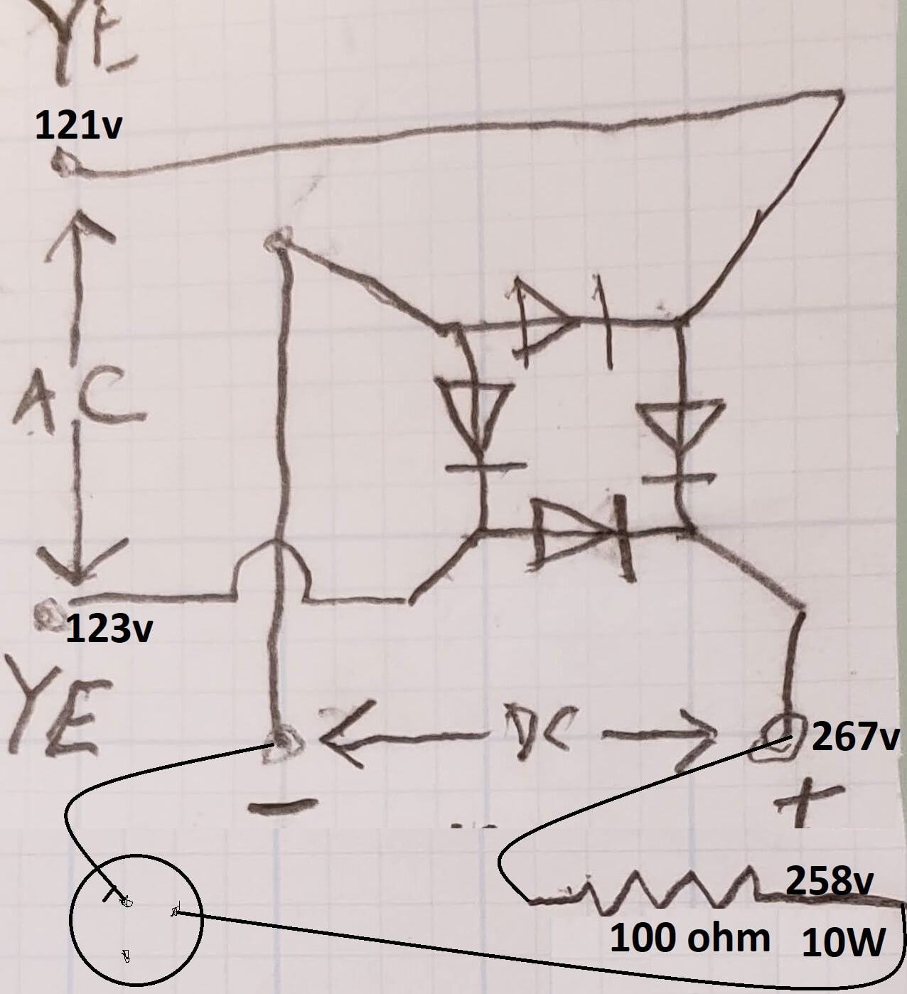
I checked the N4007 bridge rectifier to confirm the configuration is correct. I completely disconnected and disassembled them to test one by one with my multifunction tester. They all test with similar readings of between 689-695mV, but the test also showed that 2 of them had higher pF readings of 5-8. Testing new N4007 and all show 0-1pF. I assembled a new bridge, confirmed the configuration and reinstalled.
I measured the voltage with no output tubes and noted in red as “no opt”. The last measurement I took after replacing the bridge rectifier is noted in green.
Graphics included by DR
Attachments:- TFK_5384W voltage measurements (1) (122 KB)
- TFK5384W BR (134 KB)
To thank the Author because you find the post helpful or well done.
telefunken: Telefunken 5183wk Restoration
As noted in my previous comment, the voltage on the AF AMP side of the ECL86 measure near the correct 80v when tested with my analog VM. My latest test after replacing the rectifier is noted in green and is showing it now at 20v on both my DVM and AVM.
Also, I just received the speaker DIN connectors I ordered and was now able to plug in right and left speakers to the rear output jacks. I only have sound on one side. Not sure if it is left or right as there are no markings on the jacks located on the rear of the power supply panel. Facing the back of the unit it is the plug located to the left of the power cord has sound and the one to the right does not. I assumed these jacks are right and left, but maybe not?
I have been struggling to understand the internal speaker configuration as to which is right, and which is left. It has 3 wires and I assume the center pin is ground and others are right and left. No matter how I connect the speakers to that plug, the balance does not seem to make much difference.
One channel is louder and sounds better than the other. I have connected separate speakers with both grounds connected to the center post of the internal speaker output. Then connected the positive of each speaker to the right and left of the center post.
The internal speaker configuration looks like it is a 3.5-inch tweeter on one channel and the a 7x10 woofer with a 25uF non-polar cap connect to the second 3.5-inch tweeter on the other channel.
Is it possible that the output transformers are set up to send only high frequencies to one channel? Seems like most of the sound comes from the left side and it sounds normal. When I trun the balance to the right, the left speaker gets quieter and I can hear the right side more, but it sounds like it may be all high frequencies. So the symptom is the left side does not sound good, a bit distorted and no bass.
To thank the Author because you find the post helpful or well done.
telefunken: Telefunken 5183wk Restoration
Current symptom summary list:
- Amplifier sounds good and has good sound separation using the balance control when it is first turned on. After the amplifier warms up for (60-90 seconds), the sound becomes more distorted and plays mostly out of the right channel.
- With volume turned all the way down, amplifier has a consistent 60 Hertz hum, this does not change with volume.
- As the amplifier warms up (60-90 seconds), with the volume at 0, I can hear some crackling noise in the speaker.
- Power transformer seems to run warm, temperature stabilizes at about 65 degrees C
- Rear DIN speaker output jacks only have sound from jack on left side of power connector.
- Has some sound bleed through with volume at 0. This happens on radion our PU source.
To thank the Author because you find the post helpful or well done.
telefunken: Telefunken 5183wk Restoration
James,
firstly I edited some of your graphics. Hopefully, you are d'accord with the change.
If the sound gets distorted, often the grid condensers of the power tubes are leaking. This will change the working point of the power output tubes. Please check the grid condensers C83 (0.01μF) of the EL84 and C69 (1nF) of the ECL86. Especially the ECL86 is thermically somewhat critical, and tends to show grid emission.
Some bleed through with volume "0" is obviously "normal". If You look at the schematic, You will see a resistor of 270 Ohms at the lower end of both volume potentiometers.
Regards,
Dietmar
To thank the Author because you find the post helpful or well done.
telefunken: Telefunken 5183wk Restoration
Dietmar,
Thanks again for all your help. I checked the C69 and C83 capacitors, they both check good and were both newly replaced when I replaced all the other capacitors.
I was suspecting that it might be a tube issue. I have the option to pull one of the EL84’s from my Grundig stereo console model 121US. I was hesitant to do this as it has been working beautifully since I replaced all the capacitors and selenium rectifier in it about a year ago. Based on the information I have provided with the voltage measurements; do you see any potential risk to that tube by using it in the Telefunken?
Unfortunately, or fortunately, the Grundig does not use the ECL86. That tube appears to be more expensive from what I can find online. I was thinking that I can try using the EL84 from the Grundig and If I have the same symptoms, that will confirm I need to buy an ECL86.
Could the failing tube also cause the hum and the transformer to run hot?
Thanks,
James
To thank the Author because you find the post helpful or well done.
telefunken: Telefunken 5183wk Restoration
James,
I do not see a risk in checking the EL48 from the Grundig set. And I guess the original EL84 might be o.k., at least because the measured voltages and currents of the EL84 being look quite reasonable.
The excessive (?) hum might come from an elco which has lost its capacitance. Is C_1 (50μF) already replaced? What reads the ripple voltage immedately behind the rectifier bridge?
You also should check C_2 (4μF) in the 175V path. Its value could be bigger without any problem.
Did you already check the cathode voltage of the E(C)L86 which reads nominally 7V? If the "L" System shows grid current, this voltage will increase after the set is turned on.
Good luck,
Dietmar
To thank the Author because you find the post helpful or well done.
telefunken: Telefunken 5183wk Restoration
Dietmar,
C1 and C2 have been replaced.
I have attached a photo of the C1 and the rectifier replacement. This is the configuration as shown in the drawing I had attached in my previous post. This shows the voltage going into the rectifier at 121v &123v. Voltage on the + side of the rectifier is at 267v and then 258v after the 100-ohm 10w resistor.
Is there anything that might induce hum related to the placement or orientation of the new capacitor, and or the bridge rectifier?
I just checked the cathode voltage on ECL86 and I am reading 20V.
I am not clear on what the “L” System is that you refer to. Can you explain?


To thank the Author because you find the post helpful or well done.
telefunken: Telefunken 5183wk Restoration
"I just checked the cathode voltage on ECL86 and I am reading 20V. "
The ECL86 has 2 Systems: a triode ("C") and a pentode ("L") as can be seen immediately from the name of the tube. Therefore, the "L" system is the pentode system.
In the schematic of the 5183WK, the cathode voltage of the ECL86 "L" system nominally is 7V. In contrast you measure 20V (!). This means, the current of the "L" system is approx 80 mA - which is much too high. Therefore, it is most likely that the ECL86 is defective and it draws grid current.
"Is there anything that might induce hum related to the placement or orientation of the new capacitor, and or the bridge rectifier?"
Current peaks of the first elco behind the rectifier are rather high. And they are higher the greater the capacitance is and the better the elco is. These current peaks make voltage drops in the leads. It will be best to place the elco at the same position where the original elco is/was placed. So the answer is: yes! The point where the elco is connected to the chassis is critical in relation to hum.
The ECL86 has an US parallel type: 6GW8 The same holds for the EL84: 6BQ5
Regards,
Dietmar
To thank the Author because you find the post helpful or well done.
telefunken: Telefunken 5183wk Restoration
Hi Dietmar,
Thanks for the explanation. I did also test with my known good EL84 tube and the symptoms remain the same. I will go ahead and buy the new ECL86 / 6GW8, since that appears to be the issue.
I will see what I can do to get the C1 capacitor back to the original position. I bought the dual can type cap with the idea that I could keep it in the original position but lead spacing is to wide for the hole in the existing bracket. I may be able to use some stand offs to mount it just below the original position.
I will update with results of the new tube and power supply configuration.
Thanks for the help!
James
To thank the Author because you find the post helpful or well done.
telefunken: Telefunken 5183wk Restoration
Status update:
ECL 86 tube replaced:
- This seems to have resolved the issue with the sound becoming distorted after warming up.
- The transformer now stabilizes at 51C vs previous 65C
- As noted in attached (in red rectangles), the voltage readings have increased.
Please let me know if you think the voltages look within tolerance, or if there is anything else I should check.
Repositioned the elco:
- I still have 60 htz hum, but it seems a bit less.
Is it normal to have some hum?
Observations:
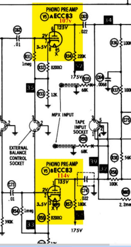
- When I pull out the ECC 83 it is completely quite, no hum
- When I try with the ECC 83 from my Grundig, I get the same hum.

To thank the Author because you find the post helpful or well done.
telefunken: Telefunken 5183wk Restoration
The Phono-pre-amp with ECC83 tube got an extra winding on mains transformer for the heaters/filament.
There you will find the potentiometer named "hum balance", connected to points x and y , wiper towards ground.
The purpose is to balance out/ minimize the crosstalk from heater filament to grids/electrodes inside the ECC83.
With "no signal at input" you should be able to adjust a minimum of hum.
This potentiometer, if defective, may be replaced by a wire-wound type only.
To thank the Author because you find the post helpful or well done.