The DC90 in Additive Mixer Circuitry
The DC90 in Additive Mixer Circuitry

Thomas Albrecht has translated the 1953 Radio-Mentor article "DC90 in additiver Mischschaltung" from German to English. Thomas based his translation on the text capture by Hans M. Knoll.
The English Version is DC90_in_Additive_Mixer_Circuitry.pdf
The original German version is DC90 in additiver Mischschaltung_v2.pdf
Mr. Knoll first uploaded this article in a thread discussing the use of triode mixers in FM front ends:
ukw_empfnangsteile_mit_trioden_als_mischer
Thank you all who contributed to this effort.
Regards,
-Joe
To thank the Author because you find the post helpful or well done.
? Additive mixer input impedance and AGC
The DC90 article from Radio-Mentor clarified several points about additive mixing with triodes.
Item b.), on page 1 listing the advantages of additive mixing, points to the increased input impedance that is found with additive mixing, as opposed to multiplicative mixing.
Increased input impedance offers potentially higher power gain, if a suitably higher impedance can be created with a transformer or LC circuit, to drive the higher input impedance with a higher signal voltage.
This property made me wonder if it would make sense to "chop" the RF preamp that drives an additive mixer at the LO frequency, to achieve a higher input impedance. A higher input impedance would be achieved, but with the enherently lower chopped transconductance, because the transconductance is averaged by the LC tuned filter load.
It would be necessary for the interface between the chopped preamp and the actual mixer to have low enough storage, such that peak transconcductance when the RF is chopped-on, would coincide in time with the peak transconductance of the mixer. Making this interface sufficiently free of storage at a useable gain is probably not practical.
So the question remains: Why is relatively low RF preamp input impedance good, while it is not good in a multi-element multiplicative mixer?
The answer lies in the fact that the preamp can be optimized for best input impedance match, noise figure and high transconductane. The multi-grid mixer does not have a resonant circuit between grids to average out the energy that might be tapped by the chopping grid, so the unchopped first grid of a mixer loads the input full time, while the signal is sampled part of the time at the LO frequency. This point is valid for mixers that take RF on the first grid, but may not be true for mixers that take RF input at the 3rd grid.
This should be one advantage of injecting the the RF input at G3, instead of G1.
(I edited this portion of the article on April 20th 2009, as my understanding of this point sharpened, comments invited)
-----------------------------------------
My open ended question arose from the reading of the DC90 article, but it is on a different topic relating to mixers:
Is it practical to add AGC voltage to the control grid of an additive mixer or, indeed, to the oscillating grid of a multiplicative converter? Has this ever been done?
I don't remember seeing it in Ghirardi's extensive coverage of AGC circuits in his 1930's book on modern radio repair.
In the case of self-oscillating converters, this AGC bias would tend to cut gain in two ways, by reducing the net chopping duty cycle of the mixing, and by reducing the DC transconductance of the tube.
Ironically, I think that the large LO swings would tend to linearize the sharp cutoff characteristic of basic triode, thus avoiding large signal distortion.
This poses another question: How does input overload occur in an additive mixer?
Regards,
-Joe
To thank the Author because you find the post helpful or well done.
AGC on grid of additive mixer

Hi Joe,
It seems likely that operating an additive self-oscillating mixer with AGC voltage on the grid would probably cause perturbations in the oscillator frequency with changes in AGC voltage.
There would also be changes in the oscillator amplitude, and while this might be OK over a certain range (except for likely frequency instability as noted above), it could stop the oscillation if it went too far, upsetting the overall function at that point.
The RF input signal, of course, also applies small instantaneous shifts to the grid voltage, so it's clear that the circuit can tolerate a certain amount of disturbance while maintaining stable oscillator frequency and amplitude. However, AGC voltages would be very large compared to the amplitude of the input signal, so there is no real comparison between the two kinds of disturbances.
Best regards,
Tom
To thank the Author because you find the post helpful or well done.
Local Oscillator control
Hi Tom,
Some of the motivation for my questions on this topic comes from the realization that most tube radios could use more AGC action. One seemingly unexplored possiblity is adding control to the oscillator signal.
Two distinct implementation possibilities arise: One is the case where the LO is separate from the mixer, and the other case is the self oscillating converter, which could be a pentagrid type, or even a triode.
Reducing the oscillator amplitude in the self-oscillating converter is generally good for AGC action, but with caveats.
One is that the tank circuit must be run with very light overdrive, so that the frequency is entirelly controlled by the L and C terms. A heavily loaded class C oscillator will drift in frequency if the load is reduced. So this caveat could be handled.
A related caveat is that any gm multiplied or dependent capacitances must be kept under control, or out of reach of the resonant tank circuit. This can be done too.
The variation in LO amplitude is perfectly reasonable, as effected by the AGC circuit, in the sense that many oscillators have their amplitude controlled by an AGC circuit. The time constants have to be controlled to avoid squegging or other instablity.
Another aspect of LO amplitude reduction is that once the local oscillator amplitude is small enough so that it's action is very linear on the mixing process, the conversion gain reduction is quite deep, while the LO amplitude may still be one volt or two.
Come to think of it, reducing conversion gain by reducing LO amplitude should handle large signals better than by cutting off the grid bias. More DC bias could be left at the usual AGC grid point, perhaps eliminating the need for a remote cutoff tube. In this case the bias range for the AGC grid could be optimised for maximum gain with weak signals, and for centering the bias point for large signals.
Another Caveat comes to mind: In the case of high frequency front ends, the tube noise generated noise might rise more quickly than the gain drop, if the tube is run near it's bandwidth limit. But in general terms, tube noise is proportional to the square of 1/gm, while gain is proportional to gm, so when gain drops, the noise does not increase as rapidly. But, again, this may worsen noise performance for medium strenght FM signals.
Well, all this means that I should just try this out some time, with one of my radios. An AA5 would be a good test bed, as it could use AGC improvement. It would be even better if someone else tried it and reported the results.
This discussion helps me consider more completely what too look for in an experiment.
Comments invited,
-Joe
To thank the Author because you find the post helpful or well done.
DC90 at VHF
I got a very poor condition Radio Set I thought was some kind of Annette LD462AB, LD471AB, LD480AB or L4D90AB.
The model label missing. A tiny corner of tube layout diagram on the back cover revealed that 1st VHF-FM stage is the DC90, not a DF97.
So it is likely a UKW-Koffersuper LD452AB as that is the only one I can find with DC90. It looks like it front and rear.
UKW-Koffersuper LD452AB "front end"
In terms of AGC it's not important as it's only used for VHF-FM. I had not seen a triode mixer/osc like this before! If /When I get it working it will be interesting to measure the amout of Local Oscillator radiated on the VHF whips.
I'm intriged by some other aspects, but I'll write about that on the LD452AB notes.
To thank the Author because you find the post helpful or well done.
LO radiation alignment
Hello Michael:
These self-oscillating triode mixers are among the most elegant and efficient circuits of the tube era. One reason for their use at the front end of portable FM sets is that their noise figure was often better than that of an RF preamp with a similar tube.
This leaves the problem of carefully aligning the LO for minimum antenna radiation and, conversely, align the LO for the least sensitivity to detuning by external antenna position variations. This brings to mind that if you touch the antenna and the radio appears to detune slightly, then the radio is probably leaking too much LO to the antenna.
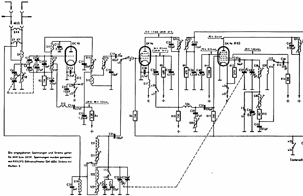
The documents for your set in the RM data base don't appear to include alignment instructions. The alignment of this class of self-oscillating front end mixer requires that the oscillating tank circuit driving the grid be balanced around it's coupling point to the antenna to cancel out nearly all LO leakage to the antenna. C11 is the 5pF trimmer cap that is trimmed with the dial at mid-band for minimum radiation to the antenna. You might use another FM radio to detect the radiation at the low end or high end of the dial, depending on whether the LO oscillates 10.7MHz lower or a higher than the station being tuned in.
After minimum antenna radiation has been secured, then you can proceed with standard LO frequency alignment.
The LO null radiation alignment must be done first because it also changes the LO frequency.
In this particular design, tuning the LO may have a tendency to slightly unbalance the tank circuit if the parasitic capacitances at tuning capacitor C5 don't remain balanced. This is the reason why balancing the LO tank with C11 may be best done with the dial tuned near the center of the band.
Keep us posted on the progress of your restoration or on any interesting findings.
Regards,
-Joe
To thank the Author because you find the post helpful or well done.
Monitoring for leakage
Fortunately I have a Yaesu VR500 pocket receiver which does 100kHz to 1300MHz in AM, AM narrow, FM, FM narrow, USB and LSB modes. I usually put it into USB and use its signal bargraph.
I also have a FET "Dip Meter/Wavemeter" originally 1.8MHz to 210MHz, but as a simple signal meter it's only better than the VR500 at LF (as the VR500 has aerial socket and whip, no coil to couple to). I added two coils for 310kHz to 495kHz band and 500KHz to 1.2MHz, but below 10MHz or so it's very poor sensitivity as a "Dip meter" but there are ways round that.
Thank you for the alignment instructions.
To thank the Author because you find the post helpful or well done.