- Produttore / Marca
- Admiral (brand) Continental Radio & Television Co.; Chicago, IL
- Anno
- 1951 ?
- Categoria
- Radio (o sintonizzatore del dopoguerra WW2)
- Radiomuseum.org ID
- 31258
-
- alternative name: Continental Radio & TV

Q = ebay objnr : 280071833704
Q = ebay objnr : 280071833704

Q = ebay objnr : 280071833704
Q = ebay objnr : 280071833704

Q = ebay objnr : 280071833704
Q = ebay objnr : 280071833704
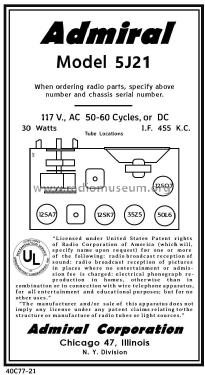
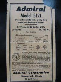
RECONSTRUCTED LABEL
Clicca sulla miniatura dello schema per richiederlo come documento gratuito.
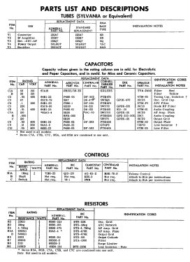
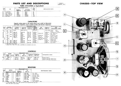
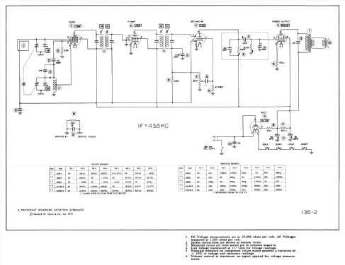
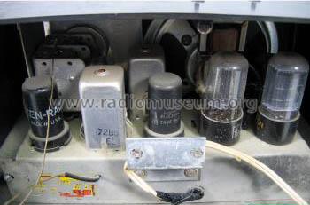
- Numero di tubi
- 5
- Principio generale
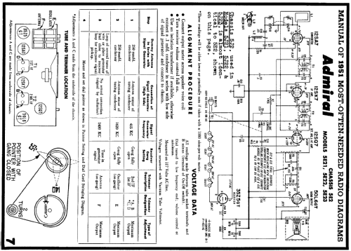
- Supereterodina (in generale); ZF/IF 455 kHz; 2 Stadi BF
- N. di circuiti accordati
- 6 Circuiti Mod. Amp. (AM)
- Gamme d'onda
- Solo onde medie (OM).
- Tensioni di funzionamento
- Alimentazione universale (doppia: CC/CA) / 117V = 110 -120 Volt
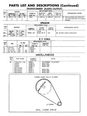
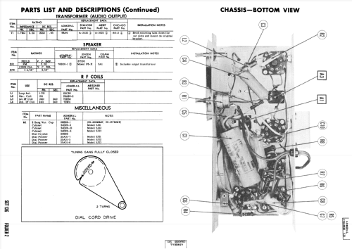
- Altoparlante
- AP magnetodinamico (magnete permanente e bobina mobile) / Ø 5 inch = 12.7 cm
- Materiali
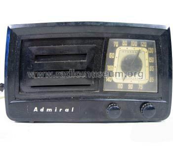
- Plastica (non bachelite o catalina)
- Radiomuseum.org
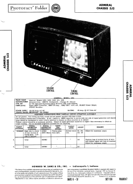
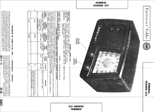
- Modello: 5J21 Ch= 5J2 - Admiral brand Continental
- Forma
- Soprammobile con qualsiasi forma (non saputo).
- Annotazioni
-
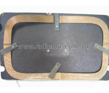
Admiral model 5J21 is an AC-DC operated superheterodyne receiver with loop antenna.
Color= Ebony, chassis 5J2 is identical to 5E2.
- Fonte esterna dei dati
- Ernst Erb
- Fonte dei dati
- Collector's Guide to Antique Radios 4. Edition
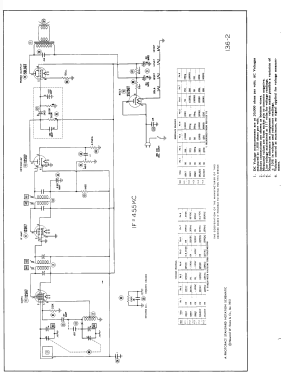
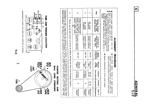
- Riferimenti schemi
- Beitman Radio Diagrams Vol. 11, 1951
- Letteratura / Schemi (1)
- Rider's Perpetual, Volume 22 = covering 1951
- Letteratura / Schemi (2)
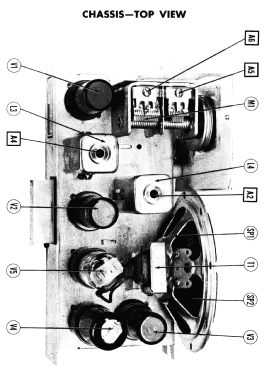
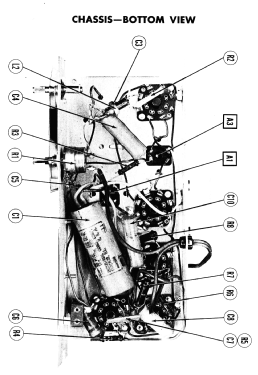
- Photofact Folder, Howard W. SAMS (Date 6-1951, Set 136, Folder 2)
- Letteratura / Schemi (3)
- Photofact Folder, Howard W. SAMS (Set 136, folder 2, dated 6-51)
- Altri modelli
-
In questo link sono elencati 3226 modelli, di cui 1329 con immagini e 2592 con schemi.
Elenco delle radio e altri apparecchi della Admiral (brand) Continental Radio & Television Co.; Chicago, IL
Discussioni nel forum su questo modello: Admiral brand: 5J21 Ch= 5J2
Argomenti: 2 | Articoli: 2
The Sams photofact with 136-2 on it at first glance on the screen looks like the 50L6 has a #1 pin connection however when enlarged/ printed it is an 8. The other schematics on the various iistings here have a #1 when enlarged or printed out. Also this schematic has the correct and easier to understand boxed in area for C7/R5 which is a combined Capacitor and resistor that looks like a 2x3 cm square flat capacitor. The boxed in area with it's individual parts diagrammed out allowed me to easily replace the combined part with 5 different resistors and capacitors .
Michael Saija, 15.Jun.19
The 50L6 tube has NO number 1 pin. The schematics show a 150 ohm resistor from pin 1 to chassis ground however in reality ( and it shows on the Sams photo's) the number 1 position on the socket is grounded to chassis. The 150 ohm resistor actually goes from the #8 pin to the #1 pin socket position and thence to chassis ground.
Michael Saija, 15.Jun.19