RF Signal Generator E Model 1
Advance Electronics / Components Ltd.; Hainault, Wrexham
- Land
- Grossbritannien (UK)
- Hersteller / Marke
- Advance Electronics / Components Ltd.; Hainault, Wrexham
- Jahr
- 1951 ?
- Kategorie
- Service- oder Labor-Ausrüstung
- Radiomuseum.org ID
- 146932
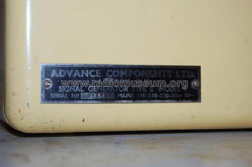
The type tag, with serial number.

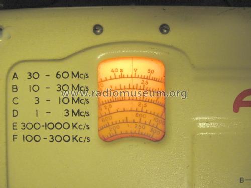
The Frequency range scale
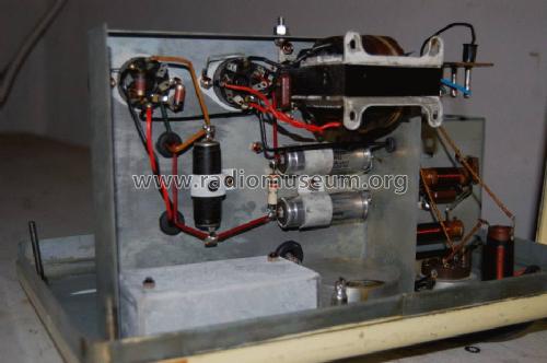
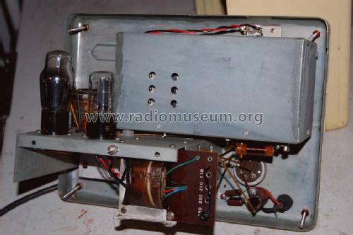
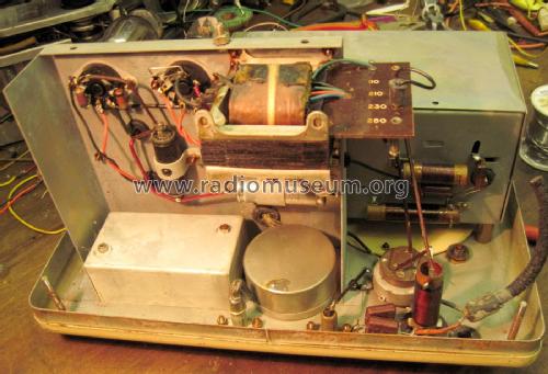
Bottom view of chassis
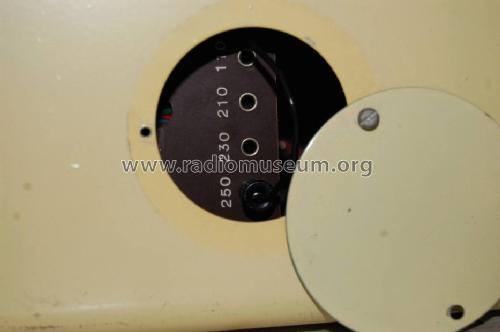
The voltage selector for mains power.


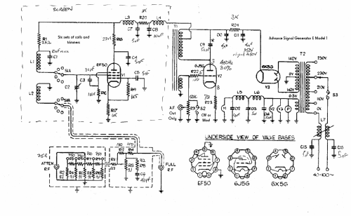
Klicken Sie auf den Schaltplanausschnitt, um diesen kostenlos als Dokument anzufordern.
- Anzahl Röhren
- 3
- Wellenbereiche
- Wellen in den Bemerkungen.
- Betriebsart / Volt
- Wechselstromspeisung / 110; 210; 230; 250 Volt
- Lautsprecher
- - - Kein Ausgang für Schallwiedergabe.
- Material
- Metallausführung
- von Radiomuseum.org
- Modell: RF Signal Generator E [Model 1] - Advance Electronics /
- Form
- Tischmodell, Zusatz nicht bekannt - allgemein.
- Abmessungen (BHT)
- 13 x 10.5 x 7.75 inch / 330 x 267 x 197 mm
- Bemerkung
-
A: 30 ... 60 MHz
B: 10 ... 30 MHz
C: 3 ... 10 MHz
D: 1 ... 3 MHz
E: 300 ... 1000 KHz
F: 100 ... 300 KHzThe Band A (30 MHz ... 60 MHz) used also for 60 MHz to 120 MHz (harmonic). It also has TV frequency markings.
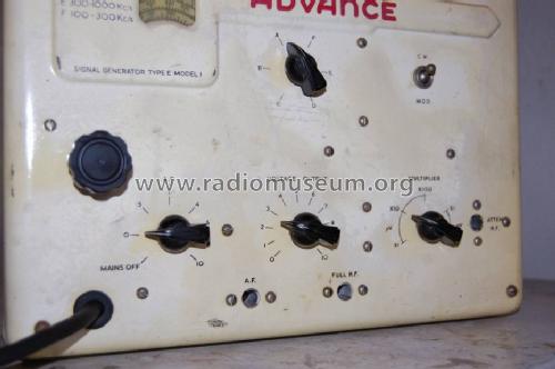
CW or 30% 400 Hz modulation.
Originally without the "Model 1" suffix, it used wartime type tubes and is otherwise identical to the 1947 Model E. The E Model 2 uses contemporary tubes and has an increased frequency range.
The sockets are old style car radio aerial type. The audio out and modulation is about 400 Hz. One RF socket is about 1V (unloaded, 50 Ohm source), the attenuated output is calibrated for a 75 Ohm load. Mains voltage is set via the circular rear cover.
Price given excludes tax and is from the 1947 advert.
- Nettogewicht
- 15 lb (15 lb 0 oz) / 6.810 kg
- Originalpreis
- 19.95 GBP
- Datenherkunft
- - - Data from my own collection
- Autor
- Modellseite von Jörgen Svensson angelegt. Siehe bei "Änderungsvorschlag" für weitere Mitarbeit.
- Weitere Modelle
-
Hier finden Sie 47 Modelle, davon 43 mit Bildern und 21 mit Schaltbildern.
Alle gelisteten Radios usw. von Advance Electronics / Components Ltd.; Hainault, Wrexham
Sammlungen
Das Modell RF Signal Generator befindet sich in den Sammlungen folgender Mitglieder.
Forumsbeiträge zum Modell: Advance Electronics: RF Signal Generator E
Threads: 1 | Posts: 3
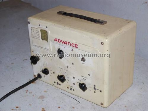
The four screws are captive to the front panel, so undo each in turn only a couple of turns.
Originally the case was not earthed. A 3A fused plug and three core flex with Earth wire to chassis makes it safer.
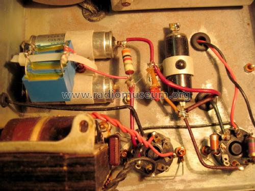
The Oscillator trimmers should not need adjustment, even after 70 years! The HT point at C11 should be connected to a 30V to 60V DC current limited PSU (10mA) via a meter to measure milliamps. Replace C10 or C11 if the current doesn't drop to less than 1mA. C11 had a slight encrustation. like leaked electrolyte on the positive end, so not surprising the current didn't drop below 7mA. Cutting it verified that C10 had dropped to less than 400uA (0.4mA) at 65V supply. So C11 was replaced with 4 x 1uF met-poly 400V parts as I had no 4uF part. The 6X5G rectifier can develop a heater cathode short thus burning out the mains transformer if there is excessive current. The 3 K Ohms, R24 will protect it if C10 later fails.
C9 was high leakage, being a paper dielectric part. All the other capacitors are Mica (silver rot rare outside USA) or ceramic and thus likely fine. The generator works fine on all bands and on 200KHz was within 1% stated tolerance.
All the connectors are the old UK style car radio type.
The stitching had failed on the handle which has a steel band inset, so the edges of the leather were glued.
The mains tap should perhaps be set one more than your nominal voltage, which you should measure as the EU 220V is allowed to be as much as 245 in the UK and 235V in Ireland. it's accessible via the rear plate. Unplug mains first as the wander plug could be live. The power switch, S3 on the audio out level, is only single pole.
Michael Watterson, 21.Sep.18