400B Chippendale Ch= W-836 or W-839, W-837, 16-E-2
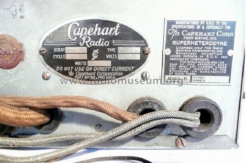
Capehart Corp.; Fort Wayne, IN - see also Farnsworth
- Pays
- Etats-Unis
- Fabricant / Marque
- Capehart Corp.; Fort Wayne, IN - see also Farnsworth
- Année
- 1933/1934

- Catégorie
- Radio - ou tuner d'après la guerre 1939-45
- Radiomuseum.org ID
- 35025
Cliquez sur la vignette du schéma pour le demander en tant que document gratuit.
- No. de tubes
- 17
- Principe général
- Super hétérodyne avec étage HF; FI/IF 180 or 465 kHz; 3 Etage(s) BF
- Circuits accordés
- 9 Circuits MA (AM)
- Gammes d'ondes
- Bandes en notes
- Particularités
- Tourne disque changeur double face; Indicateur visuel (avant oeil magique)
- Tension / type courant
- Alimentation Courant Alternatif (CA) / 60 cycles, 115 Volt
- Haut-parleur
- 2 HP
- Matière
- Boitier en bois
- De Radiomuseum.org
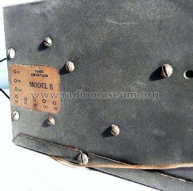
- Modèle: 400B Chippendale Ch= W-836 or W-839, W-837, 16-E-2 - Capehart Corp.; Fort Wayne, IN
- Forme
- Console de forme générique
- Remarques
-
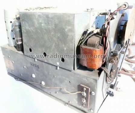
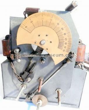
400B Chippendale, two speed changer 16-E-2, remote Aladdin possible
Cabinet: The Capehart model series 400 with Chippendale cabinet were made in five basic cabinet versions: The first models were called Chippendale 400 without suffix for 1931/32, followed by 400A (1932/33) and 400B (1933/34).
Model Chippendale 405 followed as Chippendale 405C in 1934/35, 405D, 405E, 405F and 405G (1938/39).
Then it changed style again and got model number Chippendale 410G, 410H, 410K and Chippendale 410M.After the war the models had the changer 41-E instead of 16-E: Chippendale 413N followed with a parallel Chippendale 414N, both for 1946-1948), followed by Chippendale 413P and 414P for 1948-50 as the last production.
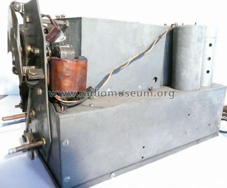
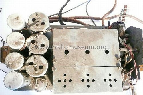
Style Chippendale was also used for Panamuse and others - and other companies used the style. See at the manufacturer Howard.Chassis = change by season: See Rider's volume 5-2 for the 8-tube tuner chassis W-836 for Capehart 400B, 402B and 404B with 58 RF, 58 osc, 2A7 mixer, 2 x 58 IF, 55 and 2 x 57 and tuning meter. But read this article about variants and different tuners for the "B". The all wave tuner chassis W-839 with 58, 2A7, 2 x 58, 56, 55, and 2 x 57 and tuning meter, also having 8 tubes, is found on Rider's 5-3. And see the 9-tube amplifier chassis W-837 - tubes 3 x 56, 4 x 2A5 and 2 x 5Z3 Rider's 5-4. Careful not to confuse it with Rider's page 1-1 to 1-4 for models 400, 401 and 402, one chassis with 13 tubes.
See here the "Common information for the Capehart model pages for the 1930s and 1940s". We show also a model page for the 400 series, either to collect photos of unknown detail and/or to show the different cabinets in comparison.
- Prix de mise sur le marché
- 995.00 $
- Source extérieure
- Ernst Erb
- Source du schéma
- Rider's Perpetual, Volume 4 = ca. 1934 and before
- Littérature
- The Incomparable Capehart
- Schémathèque (1)
- Rider's Perpetual, Volume 5 = ca. 1934 and before (5-2, 5-3 and 5-4 but also 4-3 for 400B and 4-2 for tuner 400B)
- D'autres Modèles
-
Vous pourrez trouver sous ce lien 277 modèles d'appareils, 158 avec des images et 134 avec des schémas.
Tous les appareils de Capehart Corp.; Fort Wayne, IN - see also Farnsworth
Contributions du forum pour ce modèle: Capehart Corp.; Fort: 400B Chippendale Ch= W-836 or W-839, W-837, 16-E-2
Discussions: 1 | Publications: 1
The Capehart models with suffix "B" for season 1933/34 were having the third different chassis for receiver and amplifier. They were the second generation with dual speed record changers, which were dropped after season C due to no success of that time 33 rpm records by RCA.
See a general text on Capehart Radio-Phonographs for the 1930s and 1940s here.
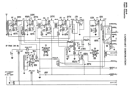
Tuner chassis 400B series
Rider's shows us 3 different tuner chassis for the "B" models.
These are used in the following models:
400B Chippendale, 402B Adam, 404B Chateau und perhaps also 300B Deauville.
Broadcast only tuner chasssis
For this chassis, Rider's shows us two different versions:
Rider's page Capehart 4-2 shows an unnumbered schematic with a mixer 58, last tube 58 and quite some differences in mixer and IF stages when compared with Rider's Capehart 5-2 with a schematic number W-836 from March 15, 1934. The first schematic has even a connection more for the "B" voltage for the AVC tube and an IF of 180 kHz! It gives us quite some checkpoints with the voltages. It shows tree and four tuned circuits. The newer schematic W-836 shows 9 tuned circuits, two more, but IF is 465 kHz!
The "All-Wave" chassis W-839, April 10, 1934
But in Rider's page Capehart 5-3 there is even a second version of the new chassis - with nearly the same tubes, but an "All-Wave chassis" instead of broadcast only. IF = 465 kHz.
It has an oscillator 56 instead of a tube 58 and is for the following bands:
Broadcast 540 to 1500 kHz
Long Wave 142 to 350 kHz
Short wave 1.4 to 3.7 MHz
Short wave 3.5 to 8.5 MHz
Short wave 8.4 to 20 MHz
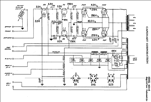
Amplifier chassis
Rider's 4-3 and Rider's 5-4 with schematic number W-837 from March 16. 1934 differ not much. The main difference is the additional wire for "B" AVC, difference cathode first tube and some parts quality (voltage).
We don't know how the different versions were named - but surely the All-Wave models must show a different name - at least in ads. Hopefully we get some more information on that.
Guests can use the contact form and are naturally invited to participate - for instance also with photos.
Every help to achieve a most complete reference work for radios and related is most welcome.
Best material is primary sources as folders, ads, fliers ... A scan of such material would be wonderful!
Ernst Erb, 09.Sep.12