Regel-Trenn-Transformator RT3
Grundig (Radio-Vertrieb, RVF, Radiowerke); Fürth/Bayern
- Country
- Germany
- Manufacturer / Brand
- Grundig (Radio-Vertrieb, RVF, Radiowerke); Fürth/Bayern
- Year
- 1959/1960
- Category
- Service- or Lab Equipment
- Radiomuseum.org ID
- 101146
-
- alternative name: Grundig Portugal || Grundig USA / Lextronix
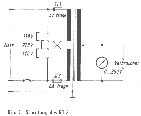
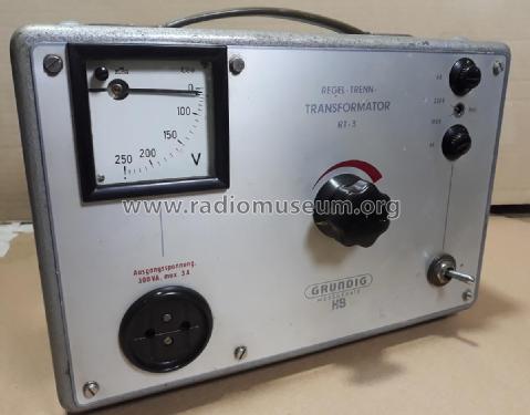


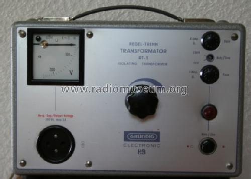
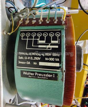
Typenschild Ringkerntransformator

Trafoabgriff mittels Kohlerad.
Click on the schematic thumbnail to request the schematic as a free document.
- Wave bands
- - without
- Power type and voltage
- Alternating Current supply (AC) / 110; 220 Volt
- Loudspeaker
- - - No sound reproduction output.
- Material
- Metal case
- from Radiomuseum.org
- Model: Regel-Trenn-Transformator RT3 - Grundig Radio-Vertrieb, RVF,
- Shape
- Tablemodel, low profile (big size).
- Dimensions (WHD)
- 300 x 215 x 190 mm / 11.8 x 8.5 x 7.5 inch
- Notes
- Ausgangsspannung: 0...250 V/300 VA.
- Net weight (2.2 lb = 1 kg)
- 12 kg / 26 lb 6.9 oz (26.432 lb)
- Price in first year of sale
- 3,950.00 BFr
- Mentioned in
- -- Original prospect or advert
- Literature/Schematics (1)
- Funk-Technik (FT) (13/1959, S. 470 / Servicegeräte)
- Author
- Model page created by Hugo Sneyers. See "Data change" for further contributors.
- Other Models
-
Here you find 6269 models, 5520 with images and 4271 with schematics for wireless sets etc. In French: TSF for Télégraphie sans fil.
All listed radios etc. from Grundig (Radio-Vertrieb, RVF, Radiowerke); Fürth/Bayern
Collections
The model Regel-Trenn-Transformator is part of the collections of the following members.
Museums
The model Regel-Trenn-Transformator can be seen in the following museums.
Literature
The model Regel-Trenn-Transformator is documented in the following literature.
Forum contributions about this model: Grundig Radio-: Regel-Trenn-Transformator RT3
Threads: 1 | Posts: 1
In meinem Grundig Regeltrenntrafo RT 3 hat kürzlich das Voltmeter den Dienst quittiert. Nach dem Ausbau sah ich einen durchgebrannten Draht des Vorwiderstandes. Das Messwerk prüfte ich dann mit dem Ohmmeter, es hat 2149 Ohm.
Nun legte ich vom Niedervoltregeltrafo Spannung an und bei ca. 32V war der Zeiger bei 250V, somit muss der Vorwiderstand 218V vernichten. Der berechnete Strom durchs Messwerk also knapp 14,9 mA. Der Vorwiderstand muss ca 14,6 Kohm haben, da nahm ich einen 15 Kohm 5 W und schaltete einen Hochohmwiderstand versuchsweise von 270 Kohm immer weiter herunter parallel, die angelegten 250V wurden korrekt angezeigt mit einem 180Kohm/2W.
Die Wärmeentwicklung blieb im Rahmen, auch nach einer Stunde Betriebszeit, so daß das Messwerk wieder eingebaut wurde und seit einigen Tagen im Dauerbetrieb immer noch die richtige Spannung anzeigt.
Eigentlich hielt ich es nicht für wichtig, da einen Beitrag zu verfassen, doch heute erreichte mich über Admin.de die Anfrage eines Gastes mit dem gleichen Problem.
Gerald Lippert
Attachments
- Foto mit Ersatzwiderständen (207 KB)
Gerald Lippert, 16.Feb.26