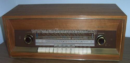
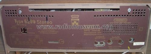
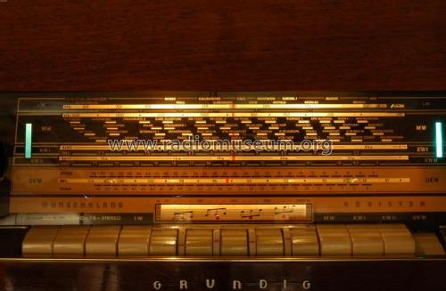
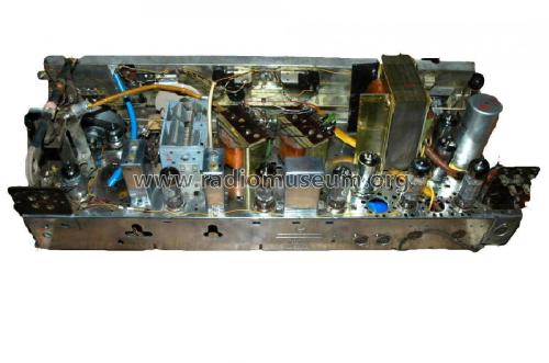
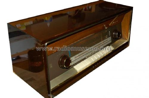
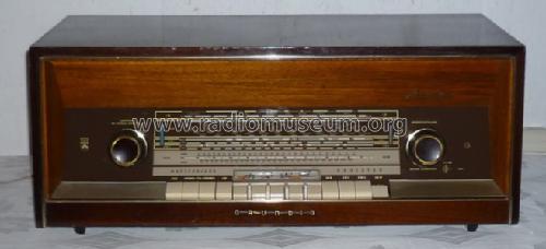
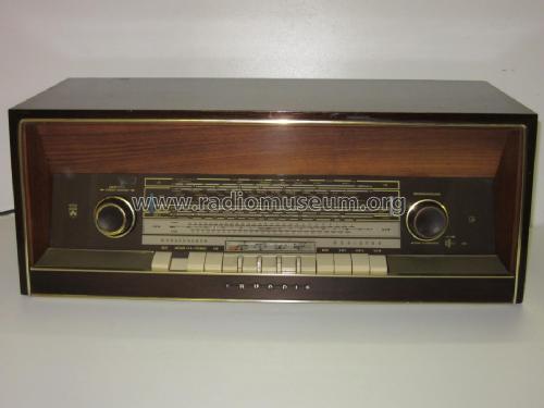
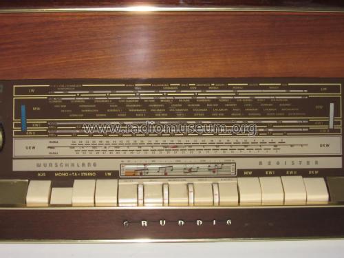
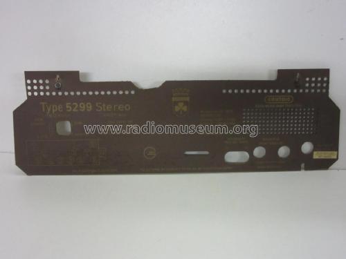
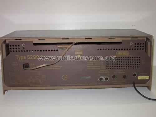
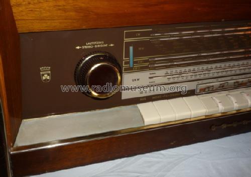
Steuergerät 5299 Stereo Nussbaum
Grundig (Radio-Vertrieb, RVF, Radiowerke)
- Country
- Germany
- Manufacturer / Brand
- Grundig (Radio-Vertrieb, RVF, Radiowerke)
- Year
- 1961/1962
- Category
- Broadcast Receiver - or past WW2 Tuner
- Radiomuseum.org ID
- 23787
-
- alternative name: Grundig Portugal || Grundig USA / Lextronix


aus ebay, Verkäufer 1966radios
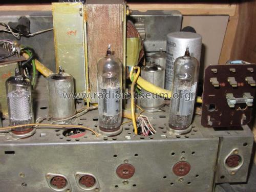
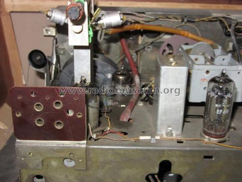
aus ebay, Verkäufer 1966radios


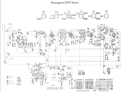
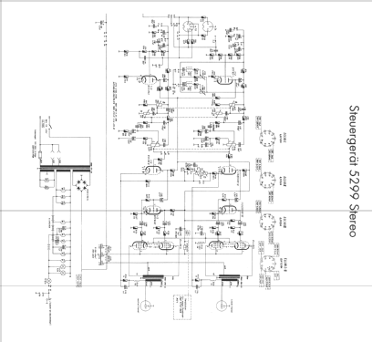
Click on the schematic thumbnail to request the schematic as a free document.
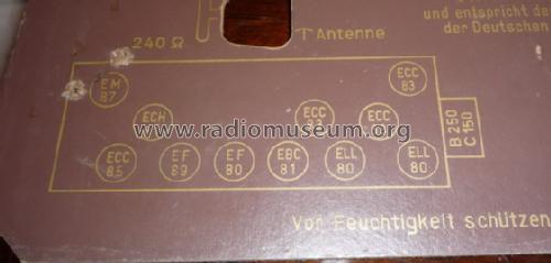
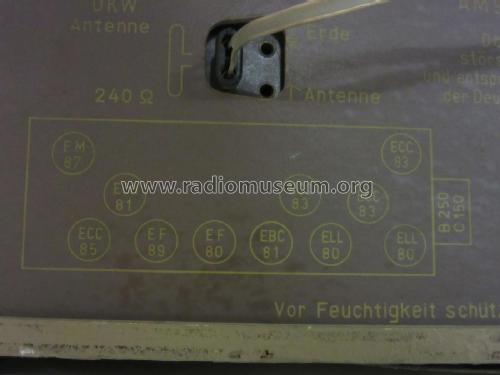
- Number of Tubes
- 11
- Number of Transistors
- Main principle
- Superheterodyne (common); ZF/IF 460/10700 kHz
- Tuned circuits
- 8 AM circuit(s) 12 FM circuit(s)
- Wave bands
- Broadcast, (BC) Long Wave (LW), 2 x SW and FM or UHF.
- Power type and voltage
- Alternating Current supply (AC) / 110; 125; 220 Volt
- Loudspeaker
- - This model requires external speaker(s).
- Power out
- 17 W (unknown quality)
- Material
- Wooden case
- from Radiomuseum.org
- Model: Steuergerät 5299 Stereo [Nussbaum] - Grundig Radio-Vertrieb, RVF,
- Shape
- Book-shelf unit.
- Dimensions (WHD)
- 670 x 280 x 275 mm / 26.4 x 11 x 10.8 inch
- Notes
-
Stereo-NF-Verstärker mit 2 Endstufen je 8,5 W. Im Katalog EM97 statt EM87.
- Net weight (2.2 lb = 1 kg)
- 13 kg / 28 lb 10.1 oz (28.634 lb)
- Price in first year of sale
- 538.00 DM
- External source of data
- Erb
- Source of data
- HdB d.Rdf-& Ferns-GrH 1961/62
- Other Models
-
Here you find 6196 models, 5420 with images and 4191 with schematics for wireless sets etc. In French: TSF for Télégraphie sans fil.
All listed radios etc. from Grundig (Radio-Vertrieb, RVF, Radiowerke)
Collections
The model Steuergerät is part of the collections of the following members.
Forum contributions about this model: Grundig Radio-: Steuergerät 5299 Stereo
Threads: 4 | Posts: 11
I recently acquired a 5299 Grundig, it has a tuning eye on the right side of the dial, I would like to know what the small bulb indicator on the left side is. Is it suppose to operate when the stereo function is activated? The bulb on mine is burned out, where can I get one to replace it? Thank you, Ross W. Hoff
Ross Hoff, 04.Mar.11
I tried to balance by adjusting the "Balance Stereo" knob but that did not have any significant change to the volume of the right channel. The volume of the left channel is significantly louder then the right channel in FM with a decoder, Tape and Phono input and in Stereo or Mono. I replaced all paper capacitors. I suspect the R1 (2x500 ohms) resistor which is the volume potentiometer or the right channel output transformer has gone bad. How do I test the R1resistor and the output transformers? I do have the schematic (Howard Sam Photofact) and but it does not illustrate the R1 resistor or the output transformer in the schematic. Please advice.
Jeff Tran, 11.Jan.11
Could anyone tell me how to restring the dial cord for the broadcast band on this radio? Mine has the cord still intact, but is off the tuning gang pulley. Any help would be greatly appreciated. Ross
Ross Hoff, 07.Sep.10
Hello, Well I have finished my first radio restoration, which is a 1961 Grundig 5299, complete with the original stereo speakers !
Well let me tell you , when I got this in the mail and opened it up, my heart sank a little. I bought this on Ebay, and was told that the cabinet was mint, and the speakers only had little chips in the top corners and thats what the photos showed. Well the stereo unit itself had been dropped on its end, and the tunning knob hardly worked. The stereo speakers had been in water, there was a water line 3 inches up the sides. This radio had a bad ELL80 tube, which you could tell just by looking at it. The plate inside glowed a pritty red. After asking many questions I ended up recaping the whole thing, papers and electolytics. I had asked in the forum about electrolytic capacitor physical size, and got a lot of good feedback. But as you will see the the pictures I went ahead a put in Sprague Atom caps, I was able to get them in. There were around 34 paper capacitors and 6 electrolytics that were replaced. The unit came with some nice tubes, which were 3 ECC83 which are Valvo's with the 45 degree getter. Those tested very well with my newly purchased Precision tube tester. I have also added 2 NOS Amperex ELL80's made in Holland. The other tubes are Buggle Boys, and Amperex made in holland tubes.
I used contact cleaner to clean all of the swithces and push buttons. The dial now works like new. I was having problems with the clutch mechanism that moved when switched from FM to SW, so I used a lubricant that is waxed base, it dries fast and does not attract dust. Just what the doctor ordered. Everything is smooth as silk.
Now came time to turn it on, when I did, nothing bad happened. The tubes all warmed up, and the ELL80 tube that had problems , no longer had problems. The surgery was a success, and a smile came across my face. I have been bitten by the bug.
Now I decided to leave the cabinet alone, and just clean it up. It does have cracks in the laquer, but it has character, and I got it to shine very nice.
The speakers needed a little attention. I had to sand the sides down, and restain. I did not laquer the sides, instead I used tung oil. They were a dull finish anyway. The tops I left alone.
The woofers had to be refoamed so I found some and did that. Also I replaced the electrolytic caps going to the mids/tweeter assembly. I was able to find 2 pin din connectors and 5 pin dins for the speaker connections. The 2 pin are at the stereo and the speakers have 5 pin.
The sound is very good and powerfull. This radio picks up a lot of stations, and with no noise in the background, on FM.. SW is good, the only thing is, I do not get much if anything on LW.
I want to thank everyone who answered my questions in the forum. It was a help.
The only thing I did not do is get pictures of the radio when I first got it. I did take one of the chassis, when I pulled it out of the cabinet, but I lost it. Thought I had saved it, but guess I did not.
So here are some pictures of my work.
Attachments
- 1 (176 KB)
- 2 (154 KB)
- DSC_2448 (2) (184 KB)
- DSC_2359 (2) (142 KB)
- DSC_2438 (2) (176 KB)
- 4 (158 KB)
- 5 (142 KB)
- 6 (183 KB)
- DSC_2376 (2) (126 KB)
Joseph Christilles, 15.Nov.06