Tube Tester 6000
Hickok Electrical Instrument Co.; Cleveland, OH
- Land
- USA
- Hersteller / Marke
- Hickok Electrical Instrument Co.; Cleveland, OH
- Jahr
- 1957–1962
- Kategorie
- Service- oder Labor-Ausrüstung
- Radiomuseum.org ID
- 113444
-
- anderer Name: Hickock


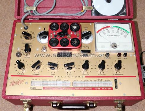
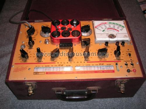
aus ebay, #115535058265, Verkäufer dr_nine
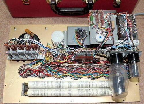
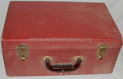
aus ebay, #115535058265, Verkäufer dr_nine
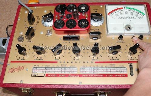

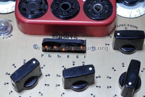
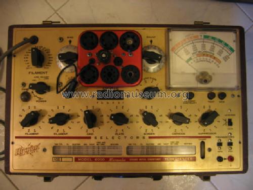
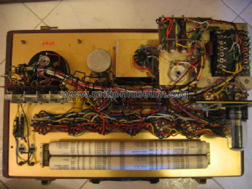
aus ebay, Verkäufer riatla

Klicken Sie auf den Schaltplanausschnitt, um diesen kostenlos als Dokument anzufordern.
- Anzahl Röhren
- 2
- Wellenbereiche
- - ohne
- Betriebsart / Volt
- Wechselstromspeisung / 110 Volt
- Lautsprecher
- - - Kein Ausgang für Schallwiedergabe.
- Material
- Gerät mit Holzgehäuse
- von Radiomuseum.org
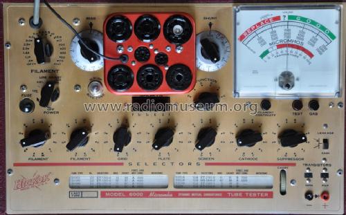
- Modell: Tube Tester 6000 - Hickok Electrical Instrument
- Form
- Tischgerät, Truhenform, meist mit Deckel (NICHT Schrägpult).
- Abmessungen (BHT)
- 265 x 185 x 425 mm / 10.4 x 7.3 x 16.7 inch
- Bemerkung
- Vereinfachtes Modell des 600; kleiner und leichter gebaut, für Servicezwecke.
- Nettogewicht
- 7.3 kg / 16 lb 1.3 oz (16.079 lb)
- Literaturnachweis
- Alan Douglas, Tube Testers and Classic Electronic Test Gear
- Weitere Modelle
-
Hier finden Sie 160 Modelle, davon 146 mit Bildern und 46 mit Schaltbildern.
Alle gelisteten Radios usw. von Hickok Electrical Instrument Co.; Cleveland, OH
Sammlungen
Das Modell Tube Tester befindet sich in den Sammlungen folgender Mitglieder.
Forumsbeiträge zum Modell: Hickok Electrical: Tube Tester 6000
Threads: 1 | Posts: 10
Gentle tube enthusiasts,
together with fellow Dale Spear, I am working on a project which involves good knowledge of the circuitry and theory of operation of 6000, 6000A and 6005 tube testers.
I have three main concerns:
1) the user's manual states that the seven sockets' contact dials have fourteen positions. However, other literature mentions twelve positions. Do they perhaps have two "standby" (= disconnected) positions, which would solve the discrepancy?
2) I particularly seem to have problems with dial 2. It should be marked 1-2-3-R-S-T-U-V-W-X-Y-Z but in the tube charts I consistently find as well a P position. Which socket's contact is connected when it is turned in P position, or which other operation is performed?
3) The "FUNCTION" switch is said to have eight positions. However, the positions used in tube testings seem to be only five: A-B-C-D and F. As long as I understand, A is used for amplifiers' tests, C for diodes' tests and D for rectifiers' tests. But I couldn't find any literature on what B and F functions are used for and what they specifically do. Does anyone have any clue?
Thanks for reading.
Marco Gilardetti, 09.Oct.09