Kobold 1720W
Loewe-(Opta); Deutschland
- Country
- Germany
- Manufacturer / Brand
- Loewe-(Opta); Deutschland
- Year
- 1956/1957
- Category
- Broadcast Receiver - or past WW2 Tuner
- Radiomuseum.org ID
- 2841
-
- alternative name: Löwe Radio


radio della mia collezione

radio della mia collezione


ebay: deepblackstarits #6565086853

ebay: deepblackstarits #6565086853


Click on the schematic thumbnail to request the schematic as a free document.
- Number of Tubes
- 5
- Number of Transistors
- Main principle
- Superheterodyne (common); ZF/IF 473/10700 kHz
- Tuned circuits
- 6 AM circuit(s) 10 FM circuit(s)
- Wave bands
- Broadcast (BC) and FM or UHF.
- Power type and voltage
- Alternating Current supply (AC) / 110; 127; 150; 220 Volt
- Loudspeaker
- Permanent Magnet Dynamic (PDyn) Loudspeaker (moving coil) - elliptical
- Power out
- 3.5 W (unknown quality)
- Material
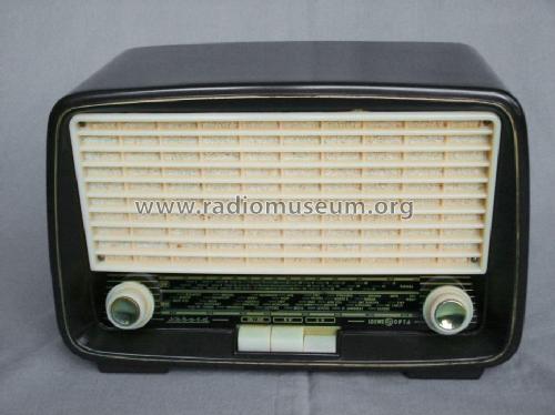
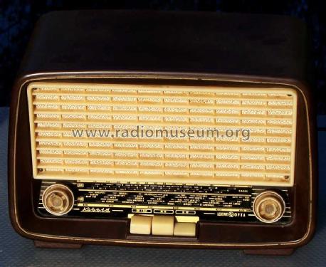
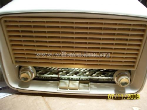
- Bakelite case
- from Radiomuseum.org
- Model: Kobold 1720W - Loewe-Opta; Deutschland
- Shape
- Tablemodel with Push Buttons.
- Dimensions (WHD)
- 280 x 180 x 140 mm / 11 x 7.1 x 5.5 inch
- Notes
-
Achtung, Spartransformator, Sekundäwicklung nur fur Röhrenheizung.
- Net weight (2.2 lb = 1 kg)
- 4 kg / 8 lb 13 oz (8.811 lb)
- Price in first year of sale
- 159.00 DM
- Source of data
- HdB d.Rdf-& Ferns-GrH 1956/57 / Radiokatalog Band 1, Ernst Erb
- Literature/Schematics (1)
- -- Schematic
- Other Models
-
Here you find 1625 models, 1366 with images and 1181 with schematics for wireless sets etc. In French: TSF for Télégraphie sans fil.
All listed radios etc. from Loewe-(Opta); Deutschland
Collections
The model Kobold is part of the collections of the following members.
Forum contributions about this model: Loewe-Opta;: Kobold 1720W
Threads: 1 | Posts: 1
Fellow Radiophiles,
I have for a long time wondered if changing the amplitude of the Local Oscillator LO into a multiplicative or additive mixer in a Super Heterodyne radio could be used as a means to control the gain through the RF, Mixer and IF signal chain. This gain control method would then be used for the Automatic Gain Control (AGC) function in the radio.
The mixer could be a 12BE6 with separate LO injection or the ECH81, which already has separate LO injection. An additive triode mixer with a separate oscillator and an intermediate gain control stage would also work.
In principle, if the amplitude of the LO into the mixer is small enough into a multiplicative mixer like the ECH81 or 12BE6 or if it is small enough for linear operation into an additive mixer, like the ECC83 or 12AT7 triodes, the IF amplitude from the mixer drops towards zero.
Well, zero really means a reduction of at least 80dB from the rated Conversion Transconductance (gmc) around 0.8mS, down to 0.08uS in the Mixer stage alone, an 80dB gain control range. This is more than the typical AGC in a mixer tube, which reduces gmc down to 10uS with -30V of AGC bias (~35dB range). A typical IF pentode, like the 12BA6, reduces its gm from 5mS to 40uS with -20V of AGC bias (~42dB range).
A conventional Mixer plus IF amp stage can vary gain up to ~80dB, but with very wide range of AGC bias voltages from 100mV to 30V, which correspond to very weak noisy stations and very loud levels of sound for strong local station.
The incremental AGC voltage is a 1:1 direct measure of the sound volume at the detector.
LO Buffer stage with variable attenuation drives the Mixer
The LO should always run with a fixed amplitude to avoid frequency drift with changing amplitude, so the control of the LO signal injection must be done between the LO and the Mixer input.
A simple low gain tube amplifier stage with sharp cutoff could be interposed between the LO and Mixer and its grid bias could be driven directly by the AGC voltage to control the LO amplitude into the mixer.
The conceptual schematic below shows the EF94=6AU6 pentode added to a small superhet (Löwe-Opta Kobold 1720w) as the AGC controlled amp between the LO and the Mixer. The sharp cutoff is an advantage to increase the effectiveness of AGC control. Distortion of the LO signal is not an issue at all, as the sinewave overdrive into the mixer is equivalent to a square wave drive.
 The LO is the triode section of the ECH81 and generates a typical ~30Vp-p oscillation at its control grid g1t, which would normally be wired directly to the LO injection grid g3h in the ECH81 heptode section.
The usual 50k load resistor at g1t in the LO is now tapped at 7k to deliver only 4Vp-p from the 30Vp-p g1t swing. The 4Vp-p swing is enough to drive the EF94 into cutoff with Vg2=100V. When there is no signal and the AGC voltage contribution is zero at the EF94 congrol grid g1, the peak plate current is 10mA. The 10mAp-p current recreates the 30Vp-p across the 3k load to be driven into the ECH81 mixer input g3h. The 3k load at the plate retains a bandwidth of 10MHz with 5pF of parasitic capacitance at the LO injection input of the mixer.
When a signal is present at the loop antenna, after frequency conversion and amplification, it will be detected by the diode section of the EBF89. The detector yields the audio output as well as the AGC voltage that is low pass filtered by R17=1Meg and C10=0.1uF into a smooth AGC voltage. The 4Vp-p LO sinewave into the EF94 control grid will self-bias the grid to -2VDC. This means the detected AGC voltage will not have any effect until it exceeds this -2V bias. The AGC bias itself also comes with a +1.2V bias from the 100Ω cathode resistor at the EBF89. So, in total, the detected AGC must exceed -3.2V before it has any effect on the gain of the EF94 LO buffer. This is a useful feature and is called AGC delay. This way, no AGC gain reduction takes place until signals are sufficiently large.
Once AGC voltage across R15 exceeds -3.2V, the EF94 will start to be biased off and the peak-to-peak plate swing will start decreasing from the maximum 30Vp-p swing. When about -7.2V of AGC is generated, which translates to -4.2VDC at the EF94 control grid, the EF94 is completely cut off and the injected LO voltage into the ECH81 g3h mixer input drops to zero. Complete cutoff will never be reached because the AGC regulation operates in a feedback loop.
This narrow AGC operating range means that the total maximum possible signal variation when the AGC is active is only from -3.2V to -7.2V. This is an excellent level of compression. Weak stations produce about -1V of AGC and are noisy but listenable. This same circuit operating with conventional AGC controlling the ECH81 and EBF89 remote cutoff grids would have an AGC variation up to -30V, which corresponds to great variations in volume from weak to strong stations.
With conventional AGC controlling remote cutoff tubes, this kind of very tight volume control over a wide range of input signal strenght would have to be done in a larger radio with multiple RF/IF stages under AGC control, or with amplified AGC.
The EF94 is, in effect, also an AGC amplifier, in that it takes a relatively small input AGC swing to control a very wide range of LO amplitude from 30Vp-p to nearly nothing.
The control grids g1h of the ECH81 and g1 of the EBF89 are both biased at ground. I added the 100Ω cathode resistors to elevate the cathodes by about 1V and thus prevent the self-generated negative contact potential of about -1V from forward biasing with hard grounded grids, which would load down the resonant tank circuits. An alternative to this cathode offset resistor is to tie the input tanks to ground via a 1Meg//100pF combination to absorb the contact potential, but which will still load the input tanks slightly.
The following circuit is only an illustrative sketch of the concept. I did not build it. Various parameters could be adjusted, like the amount of AGC delay, the total AGC range to cutoff or the fixed bias scheme for the RF and IF input grids.

Two Heptodes:
Amplitude controlled Heptode LO drives Heptode mixer
An alternative to the EF94=6AU6 gain controlled LO buffer between the LO and the mixer is a separate amplitude controlled oscillator heptode driving a heptode mixer. This oscillator could be the dual control 6BY6 heptode configured as a conventional fixed amplitude grid/cathode oscillator with the sharp cutoff g3 suppressor grid used to control the level of LO signal delivered to the plate, which then drives the g1 grid of the heptode mixer. The mixer no longer needs a remote cutoff RF input g3 grid. It can be the 6BY6 heptode with a fixed bias at the g3 RF input. The 6BY6 is the sharp cutoff version of the 6BE6.
It would have be determined empirically, which role the g1 vs g3 grids play in the mixer. The schematic shows the recommended configuration for the 6BE6, but this is a 6BY6 with sharp cutoff on both grids. Perhaps injecting the LO at g3 of T1 and the RF at g1 of T1 would yield better maximum conversion transconductance or better AGC compression.
This design also includes a 4V AGC delay with the R4=20Meg pull-up resistor. So AGC action will not start until the detected carrier exceeds -4VDC. This guarantees full maximum sensitivity for all the weaker stations. The value of R3=820k could be reduced to 470k for a 2.5V AGC delay

Löwe-Opta Kobold model 1720W as testbed for controlled LO injection
Recently, I had to repair my Löwe-Opta Kobold model 1720w. After repairs, this set became my experimental test bed for controlled LO injection.

 The AM and FM reception were both intermittent with large variations in volume during operation. Sometimes a spark of static would bring the volume back up. The usual suspects for this kind of trouble are the precision Polystyrene capacitors in the AM/FM IF transformers, which tend to develop bad connections with corrosion between the lead wires and the aluminium foil inside the cap. I had to replace all 4 AM IF capacitors inside the two IF transformer cans, plus the 2nF Polystyrene bypass cap at the g2-g4 inputs to the ECH81. The arrow marks one of the bad caps in the second IF can. This can was press-fit on the base and had to be pried out with a thin screwdriver. The can was put back with a new hand-made hold down clip to keep the can from falling off. The first IF can already came with a hold down clip and was easily removed. The FM IF caps were tubular ceramic and had no porblems. The intermittence of the 2nF cap only affected FM reception. I replaced the original 300pF at the output AM IF tanks with 274pF to force the two tuning cores a little bit toward each other during alignment and thus give me a little more overcoupled wideband response at this transformer. See "Measurement of a 455kHz IF Transformer" for more details on overcoupled IF transformer response.
Now the radio works fine. I get the full performance of the well designed ECH81-EBF89 Mixer-IF amp stages in AM. The FM front end is particularly sensitive and has low noise with its "Zwischenbasis" input circuit. It is also very stable without any FM station drift during warmup, despite having no AFC (Automatic Frequency Conrol). A well designed FM tube tuner does not drift!
Triodes have substantially lower noise (-6dB better) at 100MHz than the best RF pentodes, which suffer from partition noise at the screen grid g2. But triodes pose a design challenge to obtain the benefits of lower noise without oscillation in grounded cathode configuration. The potential for instability is caused by the Cgp (plate-grid) Miller feedback capacitance with an inductive plate load. It reflects back as a negative conductance at the grid, which then causes oscillation. The standard technique to neutralize Cgp is to feed back a compensating signal in opposite phase through a small capacitor Cn from the plate circuit to the grid circuit. This method is called neutralization, but it can get destabilized and oscillate if the match between the signals though Cgp and Cn is not good enough.
The "Zwischenbasis" alternative circuit refers to the intermeditate reference ground point of the input circuit. It is not a grounded grid stage, which is usually oscillation-proof, but has lower sensitivity and more noise than a grounded cathode stage. The grounded cathode stage can have the lowest noise but risks oscillation. With "Zwischenbasis", a tapped inductor or the tapped series capacitor pair between the grid and cathode create the intermediate tap for grounding. The grid and cathode both swing with respect to ground, but in opposite phase. "Zwischenbasis" still requires neutralization with C5=2pF, but with much lower risk of oscillation, while retaining most of the lower noise of a grounded cathode stage. This stage was common among European FM tube radios. See the FM RF input stage below with the ECC85 triode in "Zwischenbasis" configuration, using the tapped series capacitor pair C2=C3=25pF. Note the use of RF chokes like Dr3. "Drossel" is choke in German. Dr3 floats the input resonant tank at RF frequencies, while providing a DC path to ground for the grid and cathode.
Add AGC directly to the ECH81 Mixer LO input
The external AGC controlled buffer amplifier between the LO and mixer can be ommited from the conceptual schematic above. The usual short between g1t and g3h is replaced with an AC-coupling RC network. The AGC bias voltage would then feed directly into the LO injection input g3h of the ECH81 multiplicative mixer without disturbing the LO operation at g1t. AGC bias would eventually cut off the LO mixer input even though the peak-to-peak swing at this input is still the full 30Vp-p. Cutting off the LO with a large negative AGC bias at g3h does not cause any distortion in the RF signal path.
This AGC injection method would not work well with an additive mixer that has both RF and LO signals at the same grid input. Cutting off this input would distort the RF signal, just as the RF signal gets larger. A limited range of AGC is still possible and has been applied in many tube radio designs. I had direct experience with this method during my "Modifications for HiFi AM reception" of the AM-FM Zenith model Y723 from 1956. Follow the link and look about half-way down the page under "Mixer with AVC Control" for details on the limited AGC range that is possible with bias control of an additive mixer.
The data sheets of the ECH81 and the related ECH84 suggest that the cutoff at g3h is around -13V when Vg2g4=100V. This means that approximately -13V of AGC voltage added to g3h can push the entire 30Vp-p oscillator swing from the LO below the g3h cutoff, thus eliminating all conversion gain. As will be seen below from the data I took, there is still residual conversion gain when g3h is nominally 100% cutoff during the LO oscillation cycle.
A new 470pF AC-coupling cap marked up in red in the schematic separates the DC bias of g3h from g1t. The forward conduction of grids at the positive peaks clamps the oscillation between 0V and -30V. The average DC voltage of the AC-coupled 30Vp-p LO input g3h is still about -15VDC, as it is at the g1t of the LO.
So the AGC bias into g3h must be referred to the -15V average oscillation voltage. I extract this -15V DC bias from g1t with a 100k resistor bypassed with 10nF to ground (marked in red). This fixed -15VDC level serves as the reference point for the separate AGC detector 1N34A Germanium diode. I could have used the same diode type used in the FM ratio detector, an OA72, if I had one.
A 39pf cap bleeds enough IF signal into the anode of the 1N34A to develop the new AGC voltage, which is now referred to -15V. A 1MegΩ resistor and a 0.1uF cap stabilize and filter the AGC voltage into the Mixer LO input g3h. With zero signal, the anode of the 1N34A is at -15V. The internal leakage of a few uA in the 1N34A serves as a DC load for the diode, so that the anode voltage does not float way, as would be the case with a much lower leakage tube diode. A tube diode detector always needs an explicit load resistor to ground, like 1MegΩ.
At the maximum level of 13Vp-p in my RF input amplitude sweep measurements, the detected AGC voltage contributed up to -30V to the -15V g3h bias, for a net -45V bias.

Comparison of conventional AGC with LO injection controled AGC
The following first table and plot are for the original conventional AGC operation with the remote cutoff RF and IF grid inputs being fed with signal and AGC voltage.
The second table and plot are for LO injection controlled AGC method with the AGC voltage added to the LO mixer input at grid g3h. Only the ECH81 mixer stage is under AGC control. The nearly constant vertical dashed curve shows the IF stage operating at a nearly fixed gain around 120x.
The plots are shown in LOG-LOG scales with DC detected output voltage at the audio detector in the vertical axis in DC volts magnitude. This is the magnitude of the incremental DC voltage below the measured -0.35V contact potential of the audio detector in the EBF89.
The horizontal axis has both input peak signal amplitude for the red curves and stage gain for the blue curves.
The solid red curve is for the detected DC signal through the full RF+IF+Detector path. The dashed red curve is for the corresponding signal at the control grid of IF pentode EBF89. Note that these two curves are from different measurements. The IF input voltage at the EBF89 pentode was measured indirectly in a separate measurement with the signal generator driving the EBF89 control grid to produce the same detected output when the signal was originally fed into the RF input. A direct probing of the IF input would greatly detune IF transformer with the ~10-15pF probe capacitance of a 10x probe.
The solid blue curve represents stage gain for the ECH81 mixer and the dashed blue curve represents gain for the EBF89 IF stage plus Detector. The blue dot-dash curve to the right is the product of the other two blue gain curves and represents the overall voltage gain from the loop antenna to the audio detector output. The stage gains are read on the horizontal axis.
The curves should be read by first selecting an input RF level (Vpeak units) in the horizontal axis and finding the detected DC value on the solid red curve. Then follow this DC value along a horizontal line to the intersection points of the other curves. These curve intersections are then read on the horizontal axis.
The highlighted row in the table is represented in the plot with the sequence of marked data points 1 to 5 on the same horizontal line as follows:
1. 51.2mV RF input (horizontal axis, column 1) produces 9.8VDC (vertical axis, column 2) on the solid red curve
2. The IF input signal on the red-dash curve is 625mV (horizontal axis, column 3)
3. The Mixer gain is 12.7x (horizontal axis, column 4) on the solid blue line
4. The IF gain is 16x (horizontal axis, column 5) in the blue-dash curve
5. The overall gain is 199x (horizontal axis, column 6) in the blue-dot-dash curve.
Original AGC controlled by 2 Remote Cutoff Stages
| RFsig, IFsig, GAIN | RF to Vdet | IF level | Mixer Gain | IF Gain | Total Gain |
| Vpeak | Vdc | Vpeak | VIF/VRF | VDET/VIF | VDET/VRF |
| 0.0002 | 0.56 | 0.0113 | 56.5 | 87 | 4887 |
| 0.0004 | 1.29 | 0.0190 | 47.5 | 90 | 4256 |
| 0.0008 | 2.18 | 0.0320 | 40.0 | 81 | 3248 |
| 0.0016 | 3.19 | 0.0502 | 31.4 | 72 | 2255 |
| 0.0032 | 4.34 | 0.0797 | 24.9 | 60 | 1487 |
| 0.0064 | 5.64 | 0.127 | 19.8 | 48 | 944 |
| 0.0128 | 7.04 | 0.213 | 16.6 | 35 | 581 |
| 0.0256 | 8.45 | 0.372 | 14.5 | 24 | 345 |
| 0.0512 | 9.8 | 0.652 | 12.7 | 16 | 199 |
| 0.102 | 11.2 | 1.15 | 11.3 | 10 | 114 |
| 0.205 | 12.8 | 1.95 | 9.5 | 6.8 | 65 |
| 0.41 | 14.7 | 3.20 | 7.8 | 4.7 | 37 |
| 0.819 | 16.9 | 5.02 | 6.1 | 3.4 | 21 |
| 1.64 | 19.4 | 7.74 | 4.7 | 2.6 | 12 |
| 3.28 | 22.3 | 12.0 | 3.7 | 1.9 | 7.0 |
| 6.55 | 25.9 | 16.7 | 2.6 | 1.6 | 4.2 |

New AGC controlled by LO Injection
| RFsig, IFsig, GAIN | RF to Vdet | IF level | Mixer Gain | IF Gain | Total Gain |
| Vpeak | Vdc | Vpeak | VIF/VRF | VDET/VIF | VDET/VRF |
| 0.0002 | 0.56 | 0.00754 | 37.7 | 121 | 4550 |
| 0.0004 | 1.56 | 0.0147 | 36.8 | 130 | 4774 |
| 0.0008 | 3.00 | 0.0250 | 31.3 | 134 | 4188 |
| 0.0016 | 4.54 | 0.0366 | 22.9 | 134 | 3058 |
| 0.0032 | 6.09 | 0.0484 | 15.1 | 133 | 2013 |
| 0.0064 | 7.53 | 0.0596 | 9.31 | 132 | 1232 |
| 0.0128 | 8.79 | 0.0696 | 5.44 | 131 | 715 |
| 0.0256 | 9.91 | 0.0790 | 3.09 | 130 | 401 |
| 0.0512 | 10.9 | 0.0877 | 1.71 | 129 | 221 |
| 0.102 | 11.8 | 0.0947 | 0.928 | 128 | 119 |
| 0.205 | 12.6 | 0.103 | 0.502 | 126 | 63 |
| 0.41 | 13.3 | 0.109 | 0.266 | 126 | 33 |
| 0.819 | 14.0 | 0.115 | 0.140 | 125 | 18 |
| 1.64 | 15.5 | 0.128 | 0.078 | 124 | 9.7 |
| 3.28 | 22.0 | 0.193 | 0.059 | 116 | 6.8 |
| 6.55 | 33.9 | 0.339 | 0.052 | 101 | 5.3 |

I swept the signal range to unreasonable extremes, beyond what can normally appear at the loop antenna. I started with 200uV at the loop antenna, which represents an audio signal that is detectable but too noisy to listen to, because of normal atmospheric noise. I went up 16 octaves to 6.55Vpeak (13Vp-p) to look for possible output saturation and distortion effects.
My strongest local station, WRKO at 680kHz in Burlington Massachusetts, radiates 50kW. It is located 5 miles (8km) away from my home in Billerica Massachuestts. The antenna has three towers. The outer towers are 134m tall and the middle tower is 120m tall.
In my home lab in Billerica Massachusetts, after modification with the new LO injection controlled AGC, the audio detector produces -8VDC of AGC voltage with the loop antenna oriented to WRKO for peak signal, which corresponds to about 10mVpeak at the loop antenna.
I took the radio near the WRKO transmitting antennas and measured the detected DC carrier AGC voltage at distances from 400m to 1200m around the antennas. I got AGC values varying from -13.7V to -14.8V, as measured with a 10MegΩ meter. The -14.8V level corresponds to an RF signal around 1Vpeak at the loop antenna. This is about half of the 1.8Vpeak RF where the compression kink starts on the solid red curve of the second plot.
Direct comparison of the conventional vs. new AGC
The following plot makes a direct comparison of the two AGC methods, with LO injection controlled AGC in the solid curves and conventional two-stage RF and IF AGC control in the dashed curves.
The red curves are for the magnitude of the detected voltage and the blue curves are for the corresponding total overall gain for the detected DC voltage. All curve values were taken from the two tables above.
The more horizontal these curves are, the better the AGC regulation, and the lower the volume variation from weak to strong signals. The LO injection controlled AGC is clearly flatter and superior in the solid curves.

For example, the conventional AGC in the red-dash curve converted an input signal range variation from 400uV to 1.64V = 72dB into 1.29V to 19.4V = 24dB. The AGC with controlled LO injection in the solid red curve converted the same 72dB input range into 1.56V to 15.5V = 20dB. This smaller range shows better compression, and with just one stage under gain control instead of two!
Another example: 1.6mV RF signal generates 3.19V for conventional AGC, vs. 4.54V for LO injection controlled AGC. The latter is 3.1dB louder. This makes the radio more sensitive for lower signal levels.
Note that the solid and dashed curves start at the same point, thus showing the same maximum possible gain. The LO injection controlled AGC did not sacrifice the maximum possible conversion transconductace gmc of the ECH81.
The solid blue gain curve shows a very beneficial built-in AGC delay for RF signals up to 1mVpeak which corresponds to the the reasonably loud volume level associated with -3.5V of AGC. This is the vertical portion on the far right. Note how the dashed curve of conventional AGC starts reducing gain with 300uVpeak signals, when no gain reduction at all is needed. This immediate gain reduction with very weak signals in conventional AGC makes it impossible to enjoy the full sensitivity of the radio with weak signals. The -3.5V AGC delay with LO injection controlled AGC makes the radio more sensitive to weak signals. This is the 3.1dB of increased sensitivity with 1.6mVpeak RF input.
The total gain variation for conventional 2-stage AGC is 4887/12=52dB and for LO injection controlled AGC on a single stage is 4550/9.7:53dB. The highest signal level for this comparison was 1.64V, which is slightly more than the level received near the WRKO antenna.
Also note on the second plot that the ECH81 with LO injection controlled AGC can actually attenuate signals by 0.078X, as seen in the solid blue curve for conversion gain when the input RF is 1.64Vpeak. This is exceptional for the ECH81 single stage under gain control.
With this very strong 1.6Vpeak RF input, the detected DC ouput magnitude is 15.5V, which corresponds to 128mVpeak at the IF input for LO injection controlled AGC, vs 7.74Vpeak for conventional AGC. The very low signal level at the IF input makes for very linear IF gain as compared to the much larger signals of several volts with conventional AGC.
The LO injection controlled AGC relies on the deep rejection of the RF signal in the IF chain. This is very easy to achieve when the RF frequency is 1700kHz and the IF is 455kHz. At the low end of the dial, when the RF can be down to 530kHz the rejection of this RF signal through the 455kHz IF chain is still about 45dB per IF transformer, for a total of 90dB rejection with a typical pair of IF transformers. So typical IF performance is still plenty good. The nominal 45dB figure comes from earlier IF transformer measurements in a different project.
You will notice in the marked up schematic that I left a small portion of conventional AGC across R12 and R11 into the RF and IF grids. This AGC level, up to about -1V, has almost no effect on tube gain, but helps center the larger RF signals in the linear range of the RF and IF input grids. This small bleed of AGC voltage into the RF grid is attenuated to 20%VAGC=(R11+R12)/(R11+R12+R16+R17) and is attenuated into the IF grid to 7%AGC=(R11)/(R11+R12+R16+R17). The short across the band selector pins 13 and 14 keeps these resistors in the circuit in AM mode, which would otherwise follow the conventional AGC. In FM mode, these resistors serve to bias the IF grid to ground.
A related detail in the operation of controlled LO injection AGC is that with very large RF signals, the RF input grid will self bias to about half the peak-peak value of the RF signal, by virtue of local grid-leak self bias through the 1MegΩ resistor .
At the top end of the RF signal range, for signals above 2Vpeak, the gain compression is degraded beyond 15V of AGC magnitude. This is a second order effect in the ECH81 which has to do with the presence of a very large RF signal mixing with a small amount of leaked LO signal from the 30Vp-p oscillator. A small amount of 30Vp-p LO signal can leak into the RF input through the specified Cg1g3=0.3pF and cause some additive mixing. Other stray coupling paths within the ECH81 would also contribute to spurious mixing. In practice, a 2Vpeak RF signal level was never received by the loop antenna, even when very close to the 50kW transmitting antenna of WRKO with under 1Vpeak of RF at the loop antenna. There is also no sign of distortion at these very elevated RF signal levels.
This leaked LO oscillation is not an issue in the original conceptional schematic above, because the LO amplitude is attenuated as a function of AGC at the g3h grid in the ECH81.
Lack of saturation with extremely large RF signals is an inherent virtue of conventional AGC with remote cutoff tubes, which are designed to accomodate AGC voltages of tens of volts. But there is always a modest amount distortion with large signals passing through the remote cutoff characteristic of the tubes.
An ideal tube mixer for LO injection controlled AGC, would have a sharp cutoff RF grid with low mu=10, so that very large RF signals could be accomodated with a fixed bias without distortion. If this tube were a pentode or heptode, the g1g2mu would be the relevant mu. A high screen voltage combined with low mu would also extend the input linear range.
LO injection controlled AGC elsewhere?
I have looked around and asked a few engineer colleagues with RF experience and they have not seen this technique implemented. That is a little surprising, especially for today's high performance receivers. One of the key advantages for modern radios is that the IF response remains perfectly fixed regardless of signal amplitude. This is very important where the fidelity of group delay of RF pulses is very important, as is the case with RADAR. Modern digitally encoded RF signals with many channels would also benefit from an amplitude-independent IF response to maximize digital symbol integrity.
It would be nice to hear where else this technique may have been applied.
Controlled LO injection in your Radio
You can try changing the gain with controlled LO injection on any radio that you may have on the bench, simply by over-driving the Local Oscillator grid with an 0.1uF AC-coupled 50Ω impedance external generator, that is tuned to the same frequency as the LO. Once you tuned in the strongest station normally, you would apply the generator and fine-tune it for the station for peak output.
The connection to the generator keeps the LO from oscillating, so you can control the external generator amplitude down to zero and see the volume coming out of the radio drop to zero, even with the strongest stations. Keep in mind that the LO oscillates at LOfreq=RFfreq+IFfreq. For example, 1135kHz=680kHz+455kHz for the WRKO case above. Keep in mind that your generator may not be able to reach the full 30Vp-p swing that is generated by the ECH81, so you will start your experiment with a little less signal gain if your generator can only put out 20Vp-p.
This experiment also works with self-oscillating frequency converter tubes like the 12BE6, that don't have a separable LO. In the case of the 12BE6, overdrive the control grid g1. The 12BE6 is often used in sets with a hot chassis, so you you will need an isolation power transformer to make a hot chassis safe for you and for your external generator.
You may also already have observed that when the LO fails in a superhet radio no signal comes out of the radio at all.
Regards,
-Joe
Attachments
Joe Sousa, 05.Aug.24