Chiliofono I (1)
Marelli (Radiomarelli); Sesto San Giovanni (MI)
- País
- Italia
- Fabricante / Marca
- Marelli (Radiomarelli); Sesto San Giovanni (MI)
- Año
- 1931/1932
- Categoría
- Radio - o Sintonizador pasado WW2
- Radiomuseum.org ID
- 73916


Pubblicità Radiomarelli Chiliofono
Haga clic en la miniatura esquemática para solicitarlo como documento gratuito.
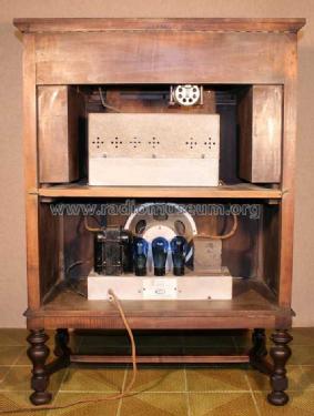
- Numero de valvulas
- 8
- Gama de ondas
- OM (onda media) solamente
- Especialidades
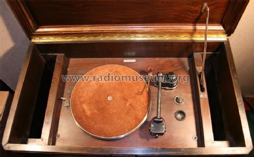
- Tocadiscos (sin cambiador autom)
- Tensión de funcionamiento
- Red: Corriente alterna (CA, Inglés = AC) / 110; 160; 220; 250 Volt
- Altavoz
- Altavoz electrodinámico (bobina de campo)
- Material
- Madera
- de Radiomuseum.org
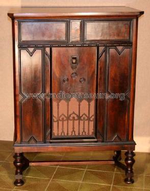
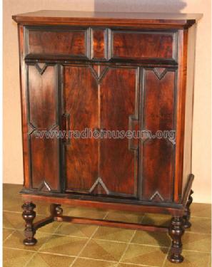
- Modelo: Chiliofono I - Marelli Radiomarelli; Sesto
- Forma
- Consola baja, patas más cortas del 50%.
- Ancho, altura, profundidad
- 800 x 1100 x 445 mm / 31.5 x 43.3 x 17.5 inch
- Precio durante el primer año
- 3,700.00 ITL
- Procedencia de los datos
- Guida Pratica Antique Radio II (2000)
- Mencionado en
- La moderna Supereterodina, Ravalico, 1938 (pag. 371)
- Documentación / Esquemas (1)
- -- Original prospect or advert
- Documentación / Esquemas (2)
- -- Schematic (La Riparazione degli Apparecchi Radio, Delforno - Colciago, Italy 1941)
- Autor
- Modelo creado por Alessandro De Poi. Ver en "Modificar Ficha" los participantes posteriores.
- Otros modelos
-
Donde encontrará 488 modelos, 379 con imágenes y 300 con esquemas.
Ir al listado general de Marelli (Radiomarelli); Sesto San Giovanni (MI)
Colecciones
El modelo Chiliofono I (1) es parte de las colecciones de los siguientes miembros.
Contribuciones en el Foro acerca de este modelo: Marelli Radiomarelli: Chiliofono I
Hilos: 1 | Mensajes: 1
Dear all,
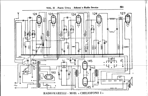
in the Forum thread ‘Old capacitor marking’ Prof. Dietmar illustrated several non-conventional volume control circuits used in the early age of the radio. This review recalled me the strange solution I found in the model ‘Chiliofono’, produced in Italy by Radiomarelli, in the very late twenties. This huge TRF receiver used a voltage divider, from the screen grid voltage (about 120VDC) to ground, to give a positive bias to the cathodes of the first two RF amplifier stages. The volume control is encircled in the diagram below. Considering the combined action of the cathode currents and of the current flowing from the power supply, the DC voltage on both cathodes roughly varied from 2V to 40V. The result was similar to the grid bias illustrated by Prof. Dietmar in the circuit of Fig. 172, the transconductance of the tubes decreasing when the positive cathode voltage was increased. The relatively high current passing in the volume control potentiometer asked for a wirewound type. By the way, the radio used a double section potentiometer, the second section wired as a variable attenuator on the phono pick-up.

in the Forum thread ‘Old capacitor marking’ Prof. Dietmar illustrated several non-conventional volume control circuits used in the early age of the radio. This review recalled me the strange solution I found in the model ‘Chiliofono’, produced in Italy by Radiomarelli, in the very late twenties. This huge TRF receiver used a voltage divider, from the screen grid voltage (about 120VDC) to ground, to give a positive bias to the cathodes of the first two RF amplifier stages. The volume control is encircled in the diagram below. Considering the combined action of the cathode currents and of the current flowing from the power supply, the DC voltage on both cathodes roughly varied from 2V to 40V. The result was similar to the grid bias illustrated by Prof. Dietmar in the circuit of Fig. 172, the transconductance of the tubes decreasing when the positive cathode voltage was increased. The relatively high current passing in the volume control potentiometer asked for a wirewound type. By the way, the radio used a double section potentiometer, the second section wired as a variable attenuator on the phono pick-up.
Emilio Ciardiello, 21.Nov.07