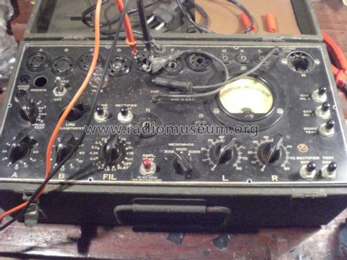
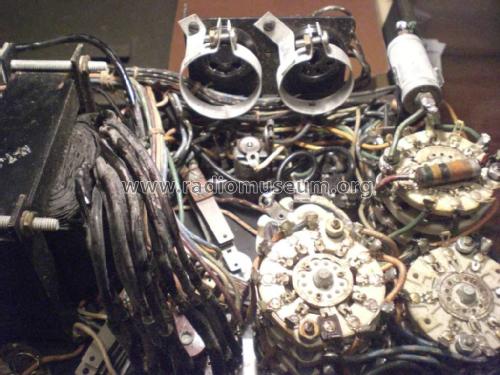
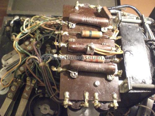
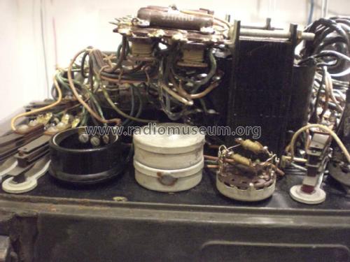
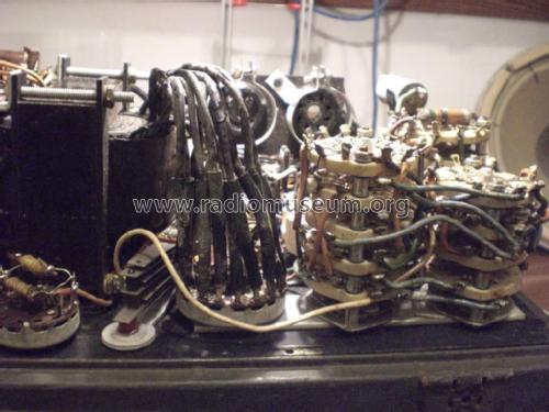
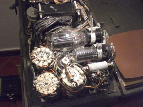
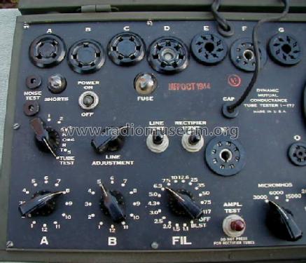
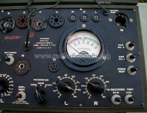
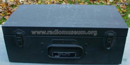
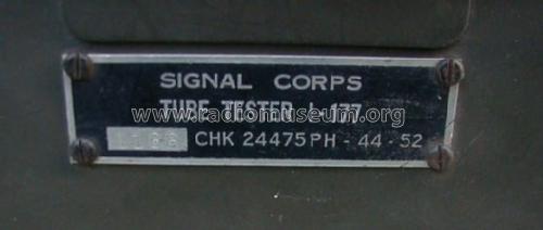
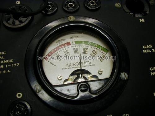
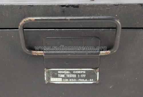
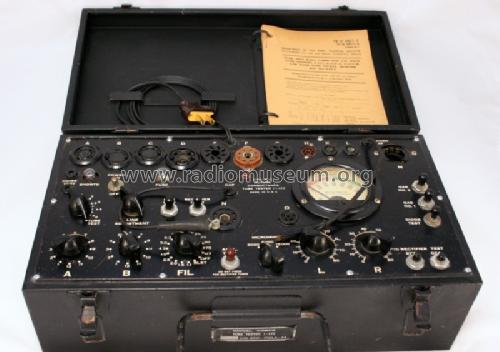
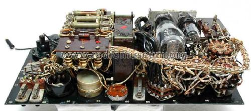
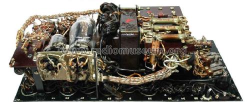
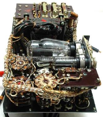
Tube Tester I-177
MILITARY U.S. (different makers for same model)
- Country
- United States of America (USA)
- Manufacturer / Brand
- MILITARY U.S. (different makers for same model)
- Year
- 1944
- Category
- Service- or Lab Equipment
- Radiomuseum.org ID
- 115467
Click on the schematic thumbnail to request the schematic as a free document.
- Number of Tubes
- 2
- Wave bands
- - without
- Power type and voltage
- Alternating Current supply (AC) / 115 Volt
- Loudspeaker
- - - No sound reproduction output.
- Material
- Metal case
- from Radiomuseum.org
- Model: Tube Tester I-177 - MILITARY U.S. different makers
- Shape
- Tablemodel, with any shape - general.
- Dimensions (WHD)
- 5.7 x 15.5 x 8.5 inch / 145 x 394 x 216 mm
- Notes
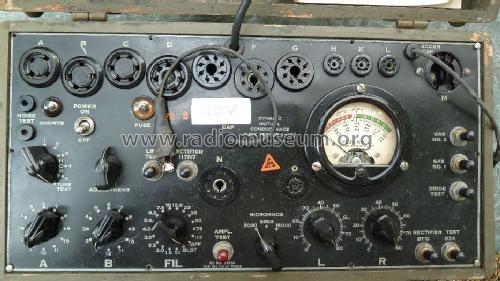
- This was the mutual conductance tube tester used by US Armed Forces since WWII.
- Net weight (2.2 lb = 1 kg)
- 8 kg / 17 lb 9.9 oz (17.621 lb)
- Source of data
- - - Manufacturers Literature
| Aggiornate il vostro Hickok I-177 | 2162 KB |
- Documents regarding this model
- Author
- Model page created by Emilio Ciardiello. See "Data change" for further contributors.
- Other Models
-
Here you find 397 models, 349 with images and 210 with schematics for wireless sets etc. In French: TSF for Télégraphie sans fil.
All listed radios etc. from MILITARY U.S. (different makers for same model)
Collections
The model Tube Tester is part of the collections of the following members.
Forum contributions about this model: MILITARY U.S.: Tube Tester I-177
Threads: 1 | Posts: 10
Gentlemen,
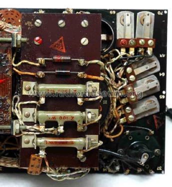
I have recently purchased a Hickok I-177 tube tester with its expansion box. As the expansion box needed an intense recabling, I am now undergoing the process of adding other European-type sockets not originally present on the board while I’m on the task.
My concern is of course the fact that most European tubes are not listed in the data sheets. I see that a lot of work on this matter has been done by Nolan Lee (that’s why I was willing to <a href="http://www.radiomuseum.org/forum/any_news_about.html">get in contact with him</a>) and other fellows here and there on the net, but many tubes are not yet covered. Just to name one type: tubes with side-contact base.
Since the set up of the ammeter on the I-177 is very easy (one potentiometer only, the other one is fixed once the scale is set to MicroMhos) I was wondering if some of you fellows developed a general method to test tubes when the tube chart is given. Tube charts are easy to find on internet, so they’re no longer a problem.
What about comparing set-up values with the TV-7 model, which seem to have more literature? Is there some kind of conversion procedure to set the I-177 once the setup for the TV-7 is given?
Any comment on this subject is welcome.
Marco Gilardetti, 12.Jan.09

