16B 16/16A-125 Version 3
Philco, Philadelphia Stg. Batt. Co.; USA
- Country
- United States of America (USA)
- Manufacturer / Brand
- Philco, Philadelphia Stg. Batt. Co.; USA
- Year
- 1934
- Category
- Broadcast Receiver - or past WW2 Tuner
- Radiomuseum.org ID
- 139600


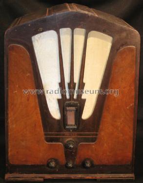
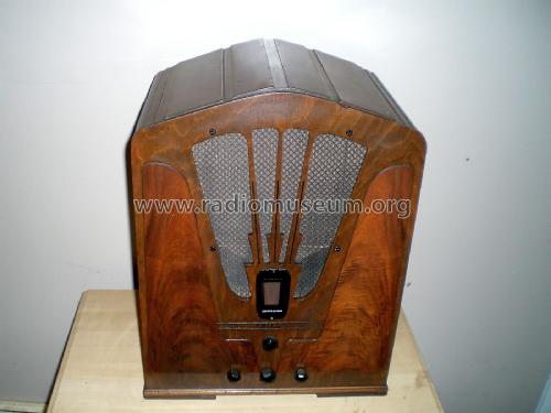
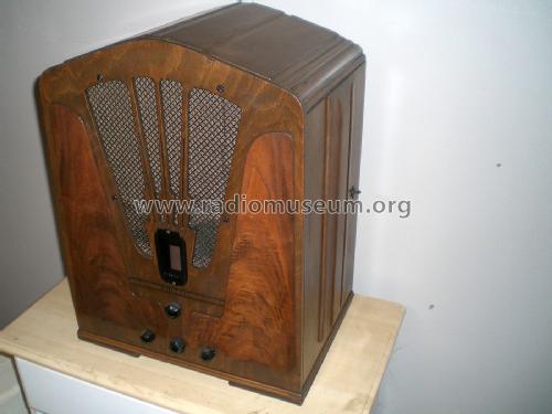
Philco 16b Front View
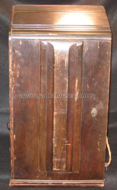
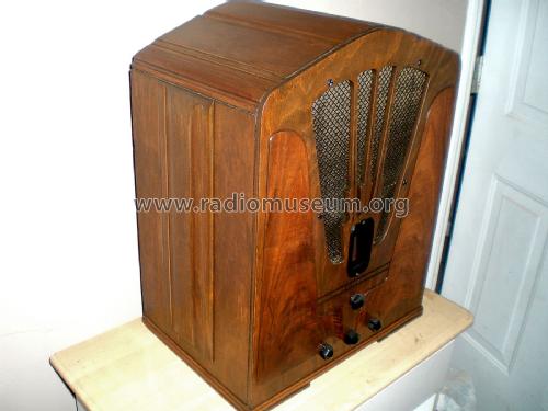
Philco 16b Side View
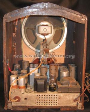
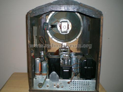
Philco 16b Rear View
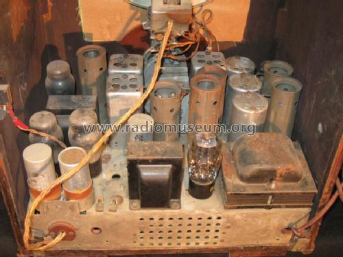
Philco 16b Chassis

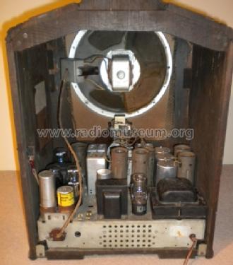
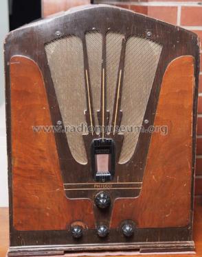
Photo by Rodney Boleyn.

Click on the schematic thumbnail to request the schematic as a free document.
- Number of Tubes
- 11
- Main principle
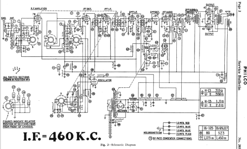
- Superhet with RF-stage; ZF/IF 460 kHz
- Wave bands
- Broadcast plus more than 2 Short Wave bands.
- Power type and voltage
- Alternating Current supply (AC) / 115 Volt
- Loudspeaker
- Electro Magnetic Dynamic LS (moving-coil with field excitation coil)
- Power out
- 10 W (unknown quality)
- Material
- Wooden case
- from Radiomuseum.org
- Model: 16B 16/16A-125 [Version 3] - Philco, Philadelphia Stg. Batt
- Shape
- Tablemodel, Tombstone = decorative upright, not cathedral but can have rounded edges.
- Dimensions (WHD)
- 17 x 22 x 12 inch / 432 x 559 x 305 mm
- Notes
-
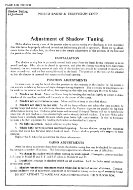
The 3rd version of the Philco 16B was introduced in Fall of 1934. The cabinet has a slightly higher peaked top than the 2nd version, with 4 broad bars running from the front of the cabinet to the back, two on either side of the peak. It uses the code 125 late chassis.
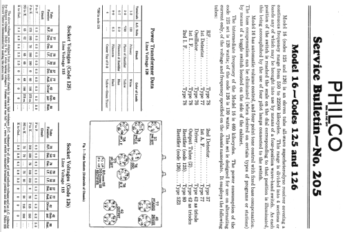
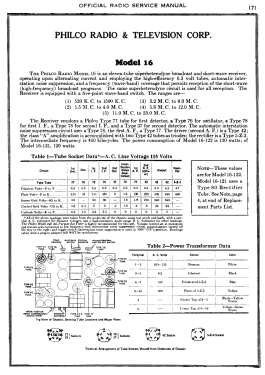
The model 16 series were high-end multi-band 11-tube radios sold by Philco for about 2 years spanning the 1933, 1934, and 1935 model years. There were two basic versions of the chassis referred to as 'early' and 'late'. Both the early and late chassis used a type 80 rectifier tube for the 16B table models, and a 5Z3 rectifier for the console models. Both chassis included dual IF-amp stages and a shadow meter (tuning aid). Both chassis were available in a version for 25-40 Hz power, and these chassis are marked as "16A" (where the -A suffix is a chassis suffix, not to be confused with the cabinet suffix on the main model number).
The early chassis used in 1933-34 included a QAVC ("quiet automatic volume control") squelch circuit to silence noise between stations. Squelch was implemented with a dedicated type 78 tube, and controlled with an on/off switch on the side and a potentiometer on the back to adjust the squelch level. The early chassis received five bands: 520-1500 kHz, 1.5-4.0 MHz, 3.2-6.0 MHz, 5.8-12.0 MHz and 11.0-23.0 MHz.
The late chassis (1934-35) eliminated the QAVC feature and repurposed its 78 tube to be an RF amplifier stage in the front end, thus maintaining the 11-tube count. The switch on the side of the cabinet was used as a bass-boost control called "Loudness". The late chassis covered a similar tuning range, but with only four bands: 550-1500 KHz, 1.5-4.1 MHz, 4.1-10.0 MHz, and 10.0-22.5 MHz.
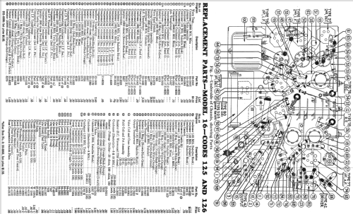
The chassis codes are as follows:
Code 121: early chassis with 80
Code 122: early chassis with 5Z3
Code 123: unknown
Code 125: late chassis with 80
Code 126: late chassis with 5Z3
Code 127: unknown
There were fifteen versions of model 16 in different cabinet styles over the three-model-year span:
Four versions of the 16B cathedral/tombstone,
Three versions of the 16L lowboy console,
Four versions of the 16X floor-type console,
Three versions of the 16RX chairside,
A special 16CPX chairside.
Stein "Cathedral & Tombstone Radios" lists only 2 bands.
- Price in first year of sale
- 90.00 $
- Source of data
- Philco Radio 1928-1942
- Circuit diagram reference
- Rider's Perpetual, Volume 6 = 1935 and before
- Literature/Schematics (1)
- Philco Service Bulletin #205
- Literature/Schematics (2)
- Cathedral & Tombstone Radios (page 190.)
- Author
- Model page created by Thomas Albrecht. See "Data change" for further contributors.
- Other Models
-
Here you find 4120 models, 2227 with images and 3768 with schematics for wireless sets etc. In French: TSF for Télégraphie sans fil.
All listed radios etc. from Philco, Philadelphia Stg. Batt. Co.; USA
Collections
The model 16B is part of the collections of the following members.