BX310A (BX310A /00)
Philips; Eindhoven (tubes international!); Miniwatt
- Paese
- Olanda
- Produttore / Marca
- Philips; Eindhoven (tubes international!); Miniwatt
- Anno
- 1951–1953
- Categoria
- Radio (o sintonizzatore del dopoguerra WW2)
- Radiomuseum.org ID
- 29832


Gerät eines Sammlerkollegen


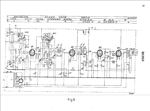
Clicca sulla miniatura dello schema per richiederlo come documento gratuito.
- Numero di tubi
- 5
- Principio generale
- Supereterodina (in generale); ZF/IF 452 kHz; 2 Stadi BF
- N. di circuiti accordati
- 6 Circuiti Mod. Amp. (AM)
- Gamme d'onda
- Onde medie (OM), lunghe (OL) e corte (OC).
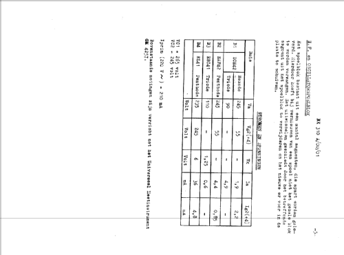
- Tensioni di funzionamento
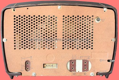
- Alimentazione a corrente alternata (CA) / 110; 125; 145; 200; 220; 245 Volt
- Altoparlante
- AP magnetodinamico (magnete permanente e bobina mobile) / Ø 15 cm = 5.9 inch
- Potenza d'uscita
- 3 W (qualità ignota)
- Materiali
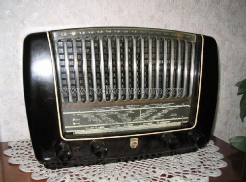
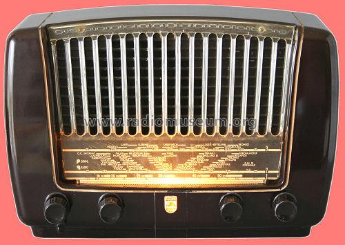
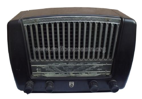
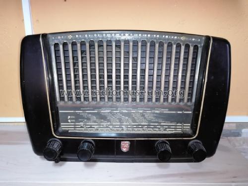
- Bachelite
- Radiomuseum.org
- Modello: BX310A - Philips; Eindhoven tubes
- Forma
- Soprammobile basso, con andamento orizzontale (grosse dimensioni).
- Dimensioni (LxAxP)
- 380 x 250 x 200 mm / 15 x 9.8 x 7.9 inch
- Annotazioni
-
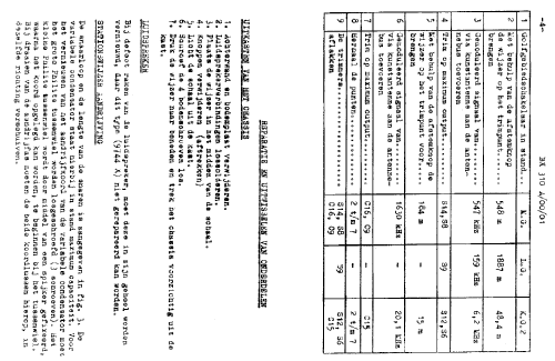
AM radio for external antenna:
- LW: 152 - 285 kHz.
- BC: 517 - 1622 kHz.
- SW: 5,92 - 18,2 MHz.
Loudspeaker: 9744X (5Ω).Dial lamp: 8045D (E10, 6,3V/320mA).In versions /53 and /90, there are some slight modifications in the parts but not in the general specifications. See the specific version schematics with this model page.
- Peso netto
- 5.9 kg / 12 lb 15.9 oz (12.996 lb)
- Fonte dei dati
- Technisch- Commercieel - Radio Vademecum Staleman
- Letteratura / Schemi (1)
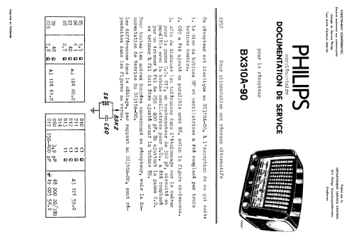
- -- Original-techn. papers.
- Letteratura / Schemi (2)
- Dépliant Nouvelle Série Philips Radio 1953, Sept. 1952
- Autore
- Modello inviato da Iven Müller. Utilizzare "Proponi modifica" per inviare ulteriori dati.
- Altri modelli
-
In questo link sono elencati 5233 modelli, di cui 4365 con immagini e 3446 con schemi.
Elenco delle radio e altri apparecchi della Philips; Eindhoven (tubes international!); Miniwatt
Collezioni
Il modello fa parte delle collezioni dei seguenti membri.
Discussioni nel forum su questo modello: Philips; Eindhoven: BX310A
Argomenti: 1 | Articoli: 6
Hello Forum,
I am restoring a Philips radio type BX310A from 1951/-52. It is generally in quite good shape but has one painful fault; namely internal arcing (= random short circuit) between primary/secondary winding -S23- S24 in the audio output transformer. Trafo's Philips code is A3 152 18.0, and iron core (E+I) size is 40*37*16mm3. Output tube is EL 41 and O/P power 2-3W? The trafo is compact and impregnated with " black tar " so very difficult to open and rewind.
This fault had very interesting symptoms and not so easy to discover. When I smoothly increased AC input voltage by Variac, so around 150V became random "crackle" audible. At the same time one or more arcs happened on tube base socket from anode pin to ground (about 5mm) also a few arcs were visible inside of the tube, especially with higher AC input. These phenomena continued with random rate. Following the anode voltage with oscilloscope showed that the voltage dropped sharply during "crackles". I changed several components and also EL41 + socket at O/P stage without success.
So my final conclusion was a high resistant short circuit between the primary and secondary windings inside of the trafo. One leg of secondary is grounded. Attached drawing shows how I think this phenomenon happens. I also tested the trafo separately with DC voltage and the "crackle " repeated. Normal ohmmeter did not indicate leaking between windings.
Does the arcing happen due to "Spark Coil" effect just like in cars??
Can somebody to advice me are there any means to repair the trafo? Due to trafo construction, rewinding of it look very difficult because of the primary section seems to be top layer. What about availability of adequate replacement trafo (new or surplus)
Best regards
Ake Nyholm
Allegati
- Ph310_audiotrafo-small (149 KB)
- EL41 anodipiiri (18 KB)
Ake Nyholm, 08.Mar.05