Pilotuner T-601
Pilot Electric Mfg. Co. (Radio Corp.); Brooklyn (NY)
- Land
- USA
- Hersteller / Marke
- Pilot Electric Mfg. Co. (Radio Corp.); Brooklyn (NY)
- Jahr
- 1947
- Kategorie
- Rundfunkempfänger (Radio - oder Tuner nach WW2)
- Radiomuseum.org ID
- 52052
-
- anderer Name: Pilot Radio & Television || Pilot Radio and Tube || Pilot Radio Corporation

Beitman


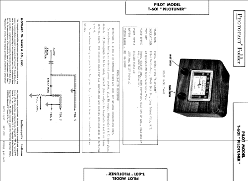


Sams Photofact Folders reference picture.
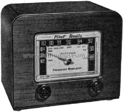
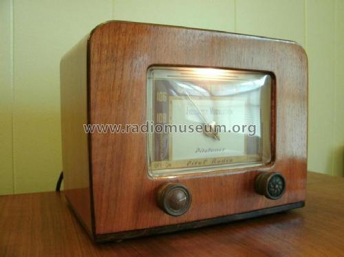
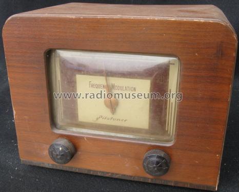
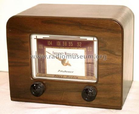
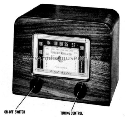
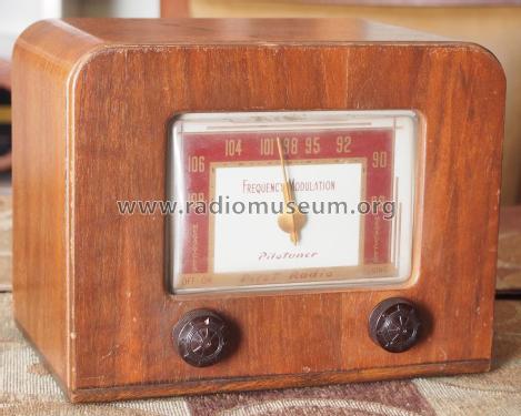
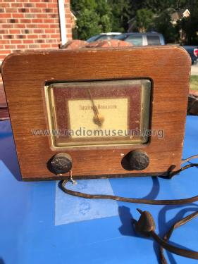
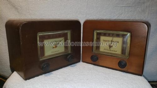
Pilot Pilotuner T-601 front view

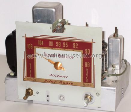
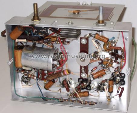
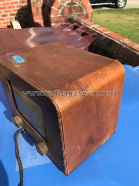
Pilot Pilotuner T-601 rear view


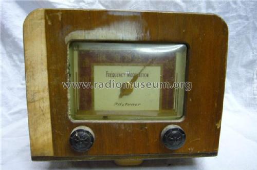


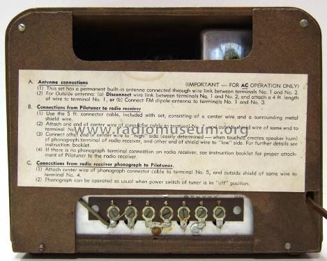
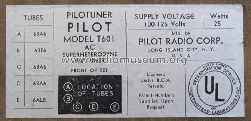
RECONSTRUCTED LABEL
Klicken Sie auf den Schaltplanausschnitt, um diesen kostenlos als Dokument anzufordern.
- Anzahl Röhren
- 5
- Hauptprinzip
- Super mit HF-Vorstufe; ZF/IF 10700 kHz
- Anzahl Kreise
- 9 Kreis(e) FM
- Wellenbereiche
- UKW-Gerät bzw. FM (keine weiteren Bänder).
- Betriebsart / Volt
- Wechselstromspeisung / 110 - 120 Volt
- Lautsprecher
- - Für Kopfhörer oder NF-Verstärker
- Material
- Gerät mit Holzgehäuse
- von Radiomuseum.org
- Modell: Pilotuner T-601 - Pilot Electric Mfg. Co. Radio
- Form
- Tischmodell, Zusatz nicht bekannt - allgemein.
- Abmessungen (BHT)
- 8.75 x 7 x 6 inch / 222 x 178 x 152 mm
- Bemerkung
- Pilot Pilotuner T601, one of the first FM receivers after approval of the new 3m-band through the FCC.
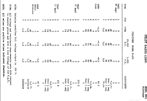
Selenium Rectifier.
Frequency range 88...110 MHz.
See also model T601A with symmetrical ratio detector.
- Nettogewicht
- 3 kg / 6 lb 9.7 oz (6.608 lb)
- Originalpreis
- 29.95 $
- Datenherkunft extern
- Ernst Erb
- Datenherkunft
- Guide to Old Radios
- Schaltungsnachweis
- Rider's Perpetual, Volume 17 = 1948 and before
- Literaturnachweis
- Collector's Guide to Antique Radios 4. Edition (Beitman Radio Diagrams 1948)
- Literatur/Schema (1)
- Photofact Folder, Howard W. SAMS (Date 11-47, Set 28, Folder 4718-27)
- Literatur/Schema (2)
- Radio Retailing (Radio & Television R.) (July 1947 page 128. September 1947 page 69.)
- Literatur/Schema (3)
- Radio mentor Mai 1949 S205
- Weitere Modelle
-
Hier finden Sie 544 Modelle, davon 273 mit Bildern und 412 mit Schaltbildern.
Alle gelisteten Radios usw. von Pilot Electric Mfg. Co. (Radio Corp.); Brooklyn (NY)
Sammlungen
Das Modell Pilotuner befindet sich in den Sammlungen folgender Mitglieder.
Forumsbeiträge zum Modell: Pilot Electric Mfg.: Pilotuner T-601
Threads: 3 | Posts: 5
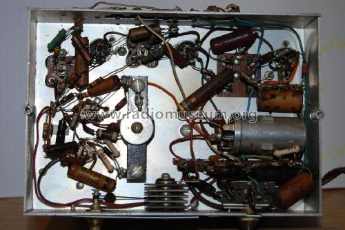
The Pilotuner T601 schemetic shows 5 tubes/valves. Mine has a 6th tube under the chassis. A 6C4. Not sure where to go from here. I replaced all caps, and all 6 tubes are good. Just trying to figure out why the 6C4?
Victor Ford, 15.May.17
In the book "Rider, J.F.; Ulsan, S.D.: FM Transmission and Reception, 2nd ed., 2nd printing, Rider, 1951" the Pilotuner and the Edwards Fidelotuner are described.
The Pilotuner
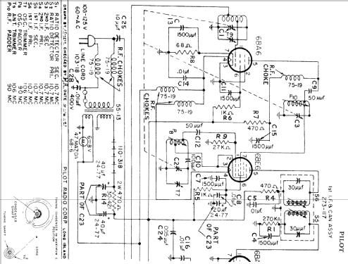
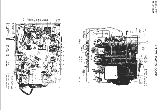
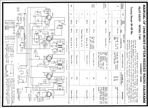
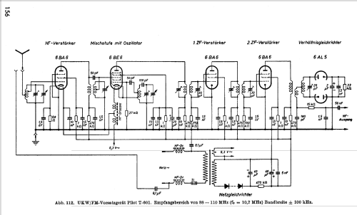
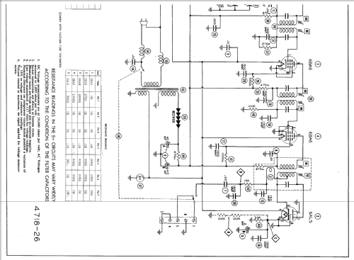
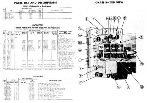
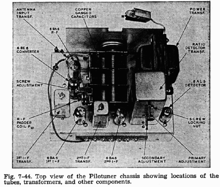
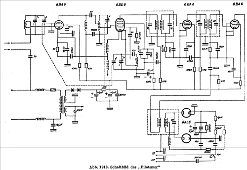
This f‑m tuner5 also employs five tubes but uses all miniature sizes with a 6AL5 duo‑diode employed as a ratio detector. Three other tubes are 6BA6 pentodes used as an r‑f amplifier and for the first and second i‑f amplifiers. A 6BE6 pentagrid tube is used as a converter. The schematic diagram for this tuner appears in Fig. 7‑43, and a top chassis view appears in Fig. 7‑44.

From the schematic diagram, a few interesting things are noted. First of all, the coils marked as P8 and P10 are shown to be variable without any internal core adjustment similar to the i‑f transformers.

Looking at the ratio detector transformer, we note that the primary does not contain any fixed capacitance for tuning purposes. The core going through the primary coil is also extended to the coil directly underneath this primary, indicating that both coils are wound on the same coil form. These features plus some other interesting properties of the tuner will now be discussed in detail.
In aligning the oscillator and r‑f stages on the low end of the f‑m band, the tuner provides for inductive padding. The r‑f section's inductive padder is designated P10 in Fig. 7‑43 and also appears in the picture of Fig. 7‑44. The interesting thing about this coil is that the variation of its inductance is simply made by changing the spacing between the coil windings. From Fig. 7‑44 the r‑f padder coil P10 is seen to consist of only two turns, and the space between these two windings is varied by means of a screw. The screw is kept in place by means of a piece of Bakelite tubing which is threaded on the inside. Upon clockwise rotation of the screw, the coil spaeing is decreased, thereby increasing the inductance, and upon counterclockwise rotation the spaeing is increased, thereby decreasing the inductance.
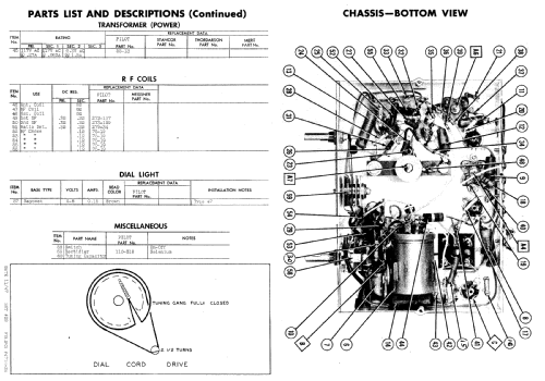
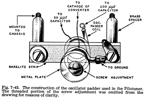
The oseillator padder P8 is located on the underside of the chassis and also consists of about two turns of wire. A drawing of this oscillator padder construction is shown in Fig, 7‑45.

The variation of the inductance of this padder is somewhat different from that for the r‑f padder P10. The spacing between the coil turns of this padder P8 are kept stationary, but the effective magnetic field about the coil is varied. Between the spacing of the winding is a thin strip of Bakelite, which is mounted above the chassis by two brass spacers. This Bakelite strip runs through the spacing of the coil and contains a threaded hole where the center of the coil winding appears. Into this hole is inserted a serew which has a round metal plate attached to the underside of the screw head. This metal plate is about 7/8 of an inch in diameter and 1/16 of an inch thick. Its diameter exceeds the diameter formed by the coil winding.
Inductance of this oscillator padder coil is varied by turning the screw in or out. This inductance variation is explained as follows: The metal plate acts as a short‑circuited secondary winding to the oscillator padder coil, which effectively acts as the primary winding. The short‑circuited secondary reflects a reactance into the primary which is capacitive. This reflected capacitance is effectively in series with the primary inductance, and therefore reduces the effective value of the inductance. With the movement of the screw and, hence the metal plate, the coupling between the plate and coil changes. As a result the mutual reactance which exists between the plate and coils also varies, which in turn varies the reflected capacitance into the coil circuit. Turning the screw so that the plate moves toward the coil increases the coupling and also increases the reflected capacitance into the primary. This increased reflected capacitance decreases the effective inductance of the oscillator tank circuit, thereby increasing its frequency. Adjusting the screw so that the plate moves away from the coil increases the effective inductance and, hence, decreases the frequency of operation of the circuit.
![]()
The primary of the ratio detector transformer has no fixed capacitance across its coil, but it still forms a tuned circuit with the output capacitance of the last i‑f tube, stray wiring capacitance, and the inherent capacitance between the coil windings. The amount of this capacitance is high enough at the 10.7‑mc i.f. to form a tuned circuit with the primary coil. Besides this feature, the physical construction of the ratio detector transformer is quite interesting. A picture of the construction of the transformer is shown in Fig. 7‑46 (A), and a detailed schematic drawing is shown in Fig. 7‑46 (B). This schematic drawing is somewhat different in appearance from the ratio detector circuit which is shown in Fig. 7‑43, but they are effectively the same in circuit operation.The tertiary coupling coil L is wound over one end of the primary coil L, which appears on the top coil form of Fig. 7‑46 (A). Because of this close coupling between L and L1, the voltage appearing across L1 is effectively in series with L but 1800 out of phase. The secondary is wound on the lower coil form. Both coil forms are mounted on a flat brass strip, and each coil form contains a variable core to change the effective inductance of the coils. The cores are adjustable by means of two screws which appear on one side of the brass strip as seen in Fig. 7‑46 (A). These screws are about 15/8 of an inch apart.
Particularly noteworthy in the construction of this transformer is the bifilar winding of the secondary coil. This bifilar winding is obtained by using a very closely spaced twin lead, which is insulated with a transparent plastic and is wound around the bottom coil form with both ends open. The plastic insulator at the ends is split, exposing two bare wires at each end. These two wires of the twin lead are shown in the drawing of Fig. 7‑46 (B) as coil A to E and coil B to D. A trace of the coil circuit across capacitor C starting at point B, would travel from point B to D, then from F to A to E. Therefore, each part of the bifilar winding L2 contributes to the inductance for the secondary tuned circuit.
Coil L must be tapped to the center of the secondary inductance to maintain the balance for the detector circuit. This tap is obtained by connecting one end of L to point F, the junction of A and D, as seen in Fig. 7‑46 (B). The complete inductance of the secondary is made up of the coil winding BDFAE, and since the length of BD is approximately equal to length AE, it is readily seen that by connecting to point F, the junction of AD we are effectively center‑tapping the coil. It is advisable that, if any trouble is suspected in the ratio detector circuit that lies within the transformer shield, the serviceman not attempt to take the circuit apart. It is suggested that the manufacturer or one of his representatives be contacted.
5Manufactured by the Pilot Radio Corp. of N.Y.C. under the brand name of "Pilotuner" and listed as model T‑601.
Dietmar Rudolph † 6.1.22, 01.Aug.13
Anlagen
- Beschreibung "Pilot T-601" (21 KB)
Dietmar Rudolph † 6.1.22, 02.Oct.04