- Pays
- Autriche
- Fabricant / Marque
- Radione (RADIO Nikolaus Eltz); Wien
- Année
- 1934/1935
- Catégorie
- Radio - ou tuner d'après la guerre 1939-45
- Radiomuseum.org ID
- 10269

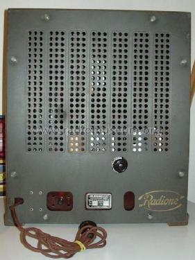

Ausschaltrelais vor dem Drehkondensator
Cliquez sur la vignette du schéma pour le demander en tant que document gratuit.
- No. de tubes
- 6
- Principe général
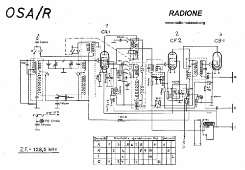
- Super hétérodyne (en général); FI/IF 128 kHz
- Circuits accordés
- 7 Circuits MA (AM)
- Gammes d'ondes
- PO, GO et OC
- Tension / type courant
- Appareil tous courants (CA / CC) / 110-220 Volt
- Haut-parleur
- HP dynamique principe inconnu
- Matière
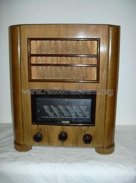
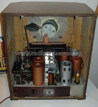
- Boitier en bois
- De Radiomuseum.org
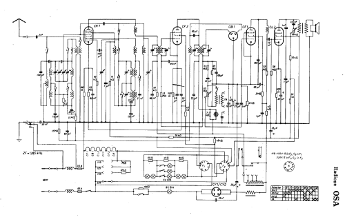
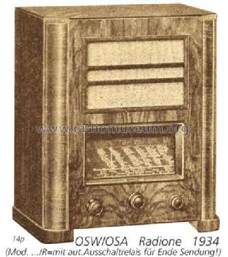
- Modèle: OSA/R - Radione RADIO Nikolaus Eltz;
- Forme
- Modèle de table vertical (pas forme catédrale)
- Dimensions (LHP)
- 415 x 485 x 275 mm / 16.3 x 19.1 x 10.8 inch
- Remarques
- OSA m.Relais; Export Schweiz (Sch=Thali)
- Poids net
- 14.4 kg / 31 lb 11.5 oz (31.718 lb)
- Prix de mise sur le marché
- 720.00 öS
- Source extérieure
- E. Erb 3-907007-36-0
- Source
- Radiokatalog Band 2, Ernst Erb
- Source du schéma
- Lange + Schenk
- Index des illustrations
- Das Modell ist im «Radiokatalog» (Erb) abgebildet.
- D'autres Modèles
-
Vous pourrez trouver sous ce lien 520 modèles d'appareils, 363 avec des images et 322 avec des schémas.
Tous les appareils de Radione (RADIO Nikolaus Eltz); Wien
Contributions du forum pour ce modèle: Radione RADIO: OSA/R
Discussions: 2 | Publications: 2
Because I own the OSA, a functional description may be of some help.
Wolfgang Holtmann, 09.Oct.10
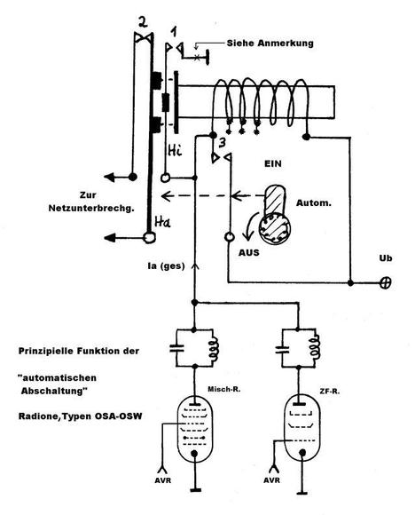
Die Geräte OSA (Allstrom) und OSW (Wechselstrom) konnten auf Wunsch mit einem Spezial-Relais zur autom. Netztrennung bei Sendeschluß des eingestellten Senders geliefert werden. Da ich den OSA mit diesem Zusatz besitze, habe ich mal die Funktion in Schrift festgelegt:

1. Vor der Inbetriebnahme des Radios, muß die Automatik zunächst ausgeschaltet sein. Über den geschlossenen Kontakt 3 ist das Relais wirkungslos. Die Netzspannung ist über den Ruhekontakt 2 durchgeschleift.
2. Nach der Aufwärmphase kann die Abschalteautomatik aktiviert werden. Dazu wird der Knopf nach rechts gedreht. Der Kurzschluß der Relaiswicklung durch Kontakt 3 wird aufgehoben und der Anodenstrom der geregelten Misch- und ZF-Röhre fließt durch diese Wicklung. (gezeichnete Stellung)
3. Normalerweise ist auf den Lieblingssender, d.h. auf einen starken Sender abgestimmt. Im herabgeregelten Zustand (hohe neg. AVR-Spannung) der genannten Röhren, ist der Gesamtanodenstrom durch die Relaiswicklung unter 6mA. Zu schwach, um eine mechanische Aktion auszulösen.
4. Bei Sendeschluß um Mitternacht wird die Trägerwelle abgeschaltet, was einen starken Rückgang der neg. AVR-Spannung bedeutet und somit einen Anstieg des Anodenstromes (über 6mA) durch die Relaiswicklung zur Folge hat.
5. Zunächst zieht der kleine Hilfsanker Hi mit Kontakt 1 an. Das geschieht ruckartig, weil ein Magnet ihn etwas festhält. Kontakt 1 läßt jetzt den maximalen Strom durch die Wicklung fließen.
6. Damit wird der schwerere Hauptanker Ha ebenfalls angezogen, der sich selbst mechanisch verriegelt! Hieran gekoppelt ist Ruhekontakt 2, welcher die Netzversorgung unterbricht und das Radio ausschaltet.
7. Daraufhin geht (langsam) die +Ub auf Null zurück, was zum Loslassen von Hilfsanker Hi, und Öffnen von Kontakt 1 führt.
8. Will man am nächsten Morgen wieder Radio hören, muß der Knopf auf der Geräterückseite(!) zuerst wieder nach links gedreht werden (Automatik = Aus) um die mechn. Verriegelung aufzuheben. Kontakt 2 schließt wieder und die Netztunterbrechung ist beseitigt. Siehe Punkt 1.
Ich frage mich ab: Wird nicht der Vorteil der autom. Abschaltung durch die umständliche -und auch noch schwer zugängliche- Handhabung wieder zunichte gemacht?
Anmerkung
Es kann zu einem ungewünschten Kurzschluß der +Ub kommen, wenn der eingestellte Sender wegfällt und gleichzeitig die Automatik von Hand ausgeschaltet wird. Dann liegt für einen Moment die nur langsam abklingende +Ub über Kontakt 3 und 1 an Masse! Da dabei die Relaiswicklung durch Kontakt 3 kurzgeschlossen wird, verzögert sich obendrein der Abfall des Hilfsankers Hi.
Um eine Beschädigung der Kontakte durch den Entladestrom des Siebelko's zu vermeiden, habe ich hinter Kontakt 1 nach Masse (Punkt X) einen 5,6 kOhm Widerstand eingefügt. Dieser begrenzt den Kurzschlußstrom, ohne die Gesamtfunktion negativ zu beeinflussen.
Wolfgang Holtmann, 16.Dec.03