T-100 series Ch= 4RT1
Raytheon Mfg. Co.; Cambridge, MA
- Pays
- Etats-Unis
- Fabricant / Marque
- Raytheon Mfg. Co.; Cambridge, MA
- Année
- 1956
- Catégorie
- Radio - ou tuner d'après la guerre 1939-45
- Radiomuseum.org ID
- 82018


Cliquez sur la vignette du schéma pour le demander en tant que document gratuit.
- No. de transistors
- 4
- Semi-conducteurs
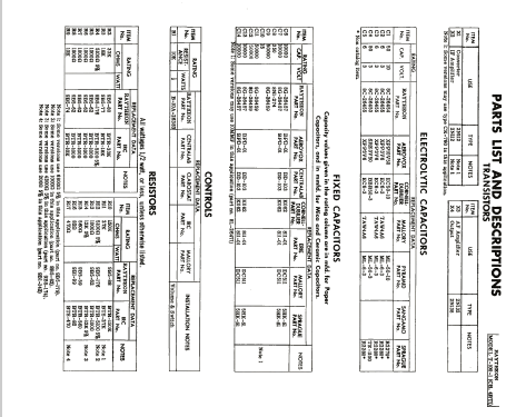
- 2N252 or. 2N112 or. CK760 2N308 or. 2N112 or. CK760 2N238 or. 2N132 2N185 or. 2N138 CK706A
- Principe général
- Super hétérodyne (en général); FI/IF 455 kHz; 2 Etage(s) BF
- Circuits accordés
- 4 Circuits MA (AM)
- Gammes d'ondes
- PO uniquement
- Tension / type courant
- Piles sèches / 9 Volt
- Haut-parleur
- HP dynamique à aimant permanent + bobine mobile / Ø 2.75 inch = 7 cm
- Matière
- Plastique moderne (pas de bakélite, ni de catalin)
- De Radiomuseum.org
- Modèle: T-100 series Ch= 4RT1 - Raytheon Mfg. Co.; Cambridge,
- Forme
- Portable, appareil de poche. Taille < 20cm
- Dimensions (LHP)
- 6.375 x 3.375 x 2 inch / 162 x 86 x 51 mm
- Remarques
- This first pocket transistor radio from Raytheon Mfg. Co., the radio model T-100, came in 5 different colors: T-100-1 = black/yellow, T-100-2 in ivory/yellow, T-100-3 in black/red, T-100-4 in ivory/red and T-100-5 in ivory/gray. Raytheon made it under the license of RCA and customized it also for Hallicrafters as model 4RT3, Airline as model BR-1102A and for Truetone as model D3715A in Turquoise. There are different schematic sources depending on the brand. Some have different values. Please check here for more information about this model family and about the differences.
Right front round brass dial with below a thumb wheel on/off/volume knob or wheel in front. In the middle a checkered grill area. The right is a free area for brand, name etc. 1 Germanium diode. No reflex circuit used. Earphone receptacle. For the semiconductors see the equivalent list by clicking the one you need on the list of the four transistors.
Interesting: For Hallicrafters the case was reversed and the thumb wheel on the front was turned into a thumb wheel on the top. Clever idea to hide its origin. See about schematics and differences between them in this explaining text.
- Source du schéma
- Beitman Radio Diagrams Vol. 16, 1956
- Littérature
- Beitman Radio Diagrams, Vol. 16, 1956 (page 132.)
- Schémathèque (1)
- Photofact Folder, Howard W. SAMS (Date 7-58, set 405, folder 15 - is actually for Truetone model D3715A - but this is the same.)
- Auteur
- Modèle crée par Egon Penker. Voir les propositions de modification pour les contributeurs supplémentaires.
- D'autres Modèles
-
Vous pourrez trouver sous ce lien 342 modèles d'appareils, 160 avec des images et 258 avec des schémas.
Tous les appareils de Raytheon Mfg. Co.; Cambridge, MA
Contributions du forum pour ce modèle: Raytheon Mfg. Co.;: T-100 series Ch= 4RT1
Discussions: 1 | Publications: 2
T-100 Series:
Here is the information on the whole model family
When I came across the first pocket transistor radio of Raytheon, I tried to write a text which fits for the whole family, including the custom made variants for other brands. Bit by bit I discovered more details so that I had to change the text on all those models.
For getting ONE venue only for such additions I write this post and link it to all those models. This enables other members and me to add data the easy way.
First what is now the (remaining) text on each model:
This first pocket transistor radio from Raytheon Mfg. Co., the radio model T-100, came in 5 different colors: T-100-1 = black/yellow, T-100-2 in ivory/yellow, T-100-3 in black/red, T-100-4 in ivory/red and T-100-5 in ivory/gray. Raytheon made it under the license of RCA and customized it probably also for Hallicrafters as model 4RT3, Airline as model BR-1102A and for Truetone as model D3715A in Turquoise. There are different schematic sources, depending on the brand. Some have different values. Please check here for more information about this model family and about the differences.
Right front round brass dial with below a thumb wheel on/off/volume knob or wheel in front. In the middle a checkered grill area. The right is a free area for brand, name etc. 1 Germanium diode. No reflex circuit used. Earphone receptacle. For the semiconductors see the equivalent list by clicking the one you need on the list of the four transistors.
Interesting: For Hallicrafters the case was reversed and the thumb wheel on the front was turned into a thumb wheel on the top. Clever idea to hide its origin. See about schematics and differences between them in this explaining text.
This enables you to browse the models and to reach this text here.
Some more information for those models:
First version was the Raytheon T-100, chassis 4RT1
There are five different color variants which became each a different model identification.
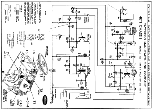
This series is reflected in SAMS Photofact date 9-56, set 331, folder 11 for that chassis 4RT1. It is common practice to publish schematics after the model is on the market - for not revealing information to competitors. Sometimes publishers like SAMS could even publish the schematics only some years later. This has different reasons and is not the case here. I think this schematic is reflected in SAMS TMS-2 too. The same transistors are given as below in Beitman.
Also in 1956, Beitman published the chassis 4RT1 with the models T-100-1, T-100-2, T-100-3, T-100-4 and T-100-5 in volume R-16 on page 132.
The transistors given are 2 x 2N112 or CK-760, 2N132 and 2N138 (with heat sink). The crystal detector is given as CK-706A. We don't use the hyphen. SAMS names the same transistors and notes for the diode: Raytheon 1N295 or CK-706A plus Sylvania 1N60.
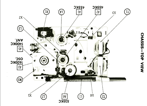
It is interesting to see that on chassis 4RT1 a 19 ohm speaker is used and therefore also an output transformer with a primary impedance of 1.9 kOhm and sec. 19 Ohm. The audio input transformer is 4:1 (resistance 880 to 120 Ohm). The 2 gang tuning capacitor has on antenna loop stick 17 - 190 pF and on the Osc. Coil 14 - 120 pF. Tuning range is 540 - 1600 kc. The power rating on the 9 volt battery should be 12 mA with no signal.
The other versions with chassis 4RT3
For the model D3715A from True Tone Radio Mfg. there is SAMS Photofact date 7-58, set 405, folder 15. I could not find a schematic for Hallicrafters 4RT3 - but since the Hallicrafters uses the chassis as model name, we know which one it is. For BR-1102A there is a Beitman R-18 schematic from 1958. It lists the transistors 2N140, 2N139, 2N109 and 2N109. Otherwise it is very similar to the other Beitman.
The main differences between chassis 4RT1 and 4RT3 are:
The interstage transformer (audio input) is 3:1. The audio output transformer has an impedance of primary 1215 Ohm and sec. 15 Ohm for 15 Ohm speaker. The 2 gang tuning capacitor has on antenna loop stick 17 - 195 pF and on the Osc. Coil 13 - 113 pF. The tuning-range is broadcast 540 - 1620 kc. The power rating on the 9 volt battery should be 10.7 mA with no signal.
The transistors are here as original types: Converter 2N252 (replacement RCA 2N140, Raytheon 2N415), IF amplifier 2N308 (RCA 2N247), AF amplifier 2N238 (CBS 2N180, RCA 2N217, Raytheon 2N362) and OUtput 2N185 (CBS 2N180, RCA 2N109, Raytheon 2N359 or Sylvania 2N383).
By knowing all this, one wonders where the chassis 4RT3 was made ... And: Is there also a chassis 4RT2? Maybe we get some information from members or guests - who can use the contact form.
Ernst Erb, 29.Aug.10