- Hersteller / Marke
- Siemens (& Halske, -Schuckert Werke SSW, Electrogeräte); Berlin, München
- Jahr
- 1941 ?
- Kategorie
- Rundfunkempfänger (Radio - oder Tuner nach WW2)
- Radiomuseum.org ID
- 5328
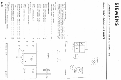
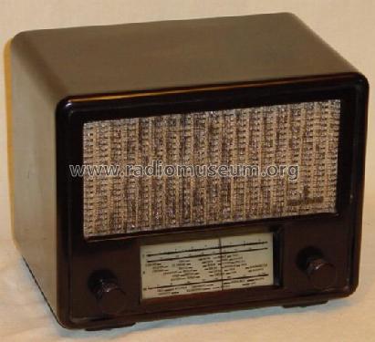
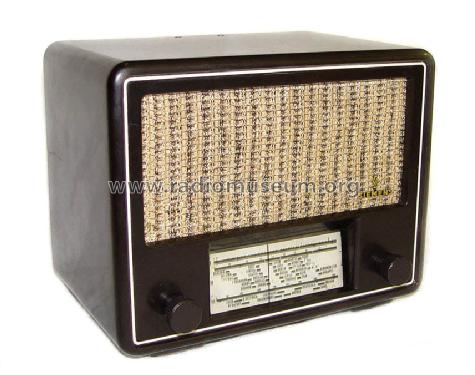
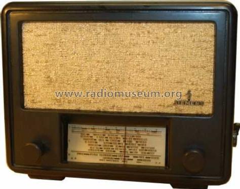
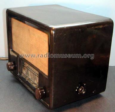
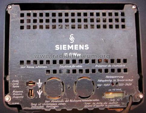
Gehäuse Aussen gereinigt und Poliert
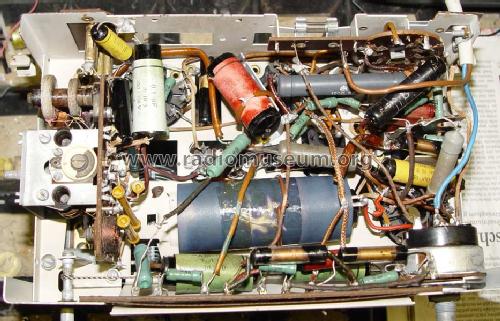
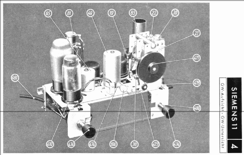
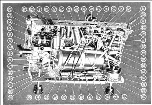
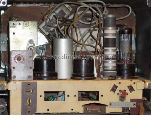
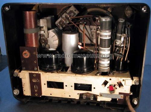
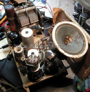
Chassis Unten nach Reinigung
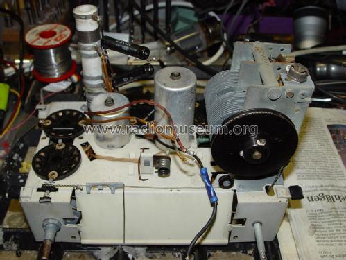
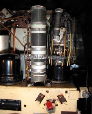
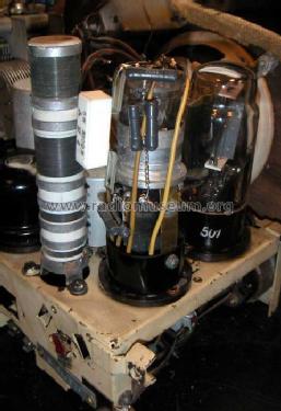
Chassis Oben nach Reinigung
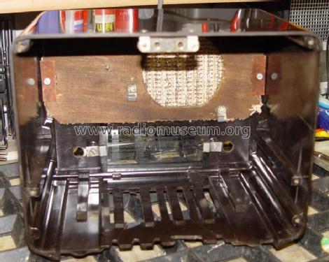
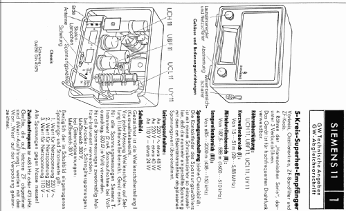
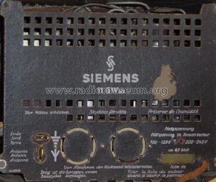
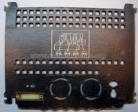
Gehäuse Innenseite
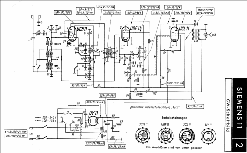
Klicken Sie auf den Schaltplanausschnitt, um diesen kostenlos als Dokument anzufordern.
- Anzahl Röhren
- 4
- Hauptprinzip
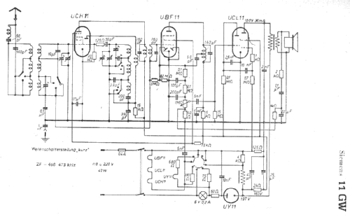
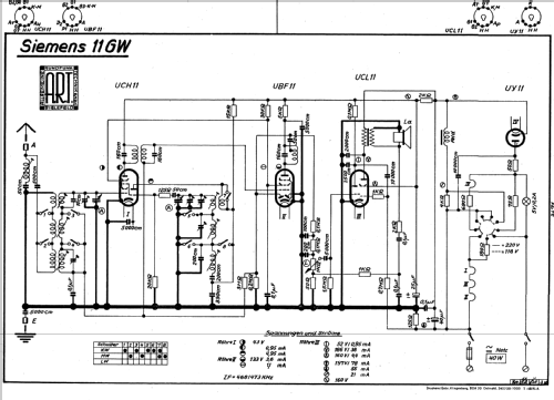
- Superhet allgemein; ZF/IF 468 kHz; Exportmodell
- Anzahl Kreise
- 5 Kreis(e) AM
- Wellenbereiche
- Langwelle, Mittelwelle und Kurzwelle.
- Betriebsart / Volt
- Allstromgerät / 110/220 Volt
- Lautsprecher
- Dynamischer LS, mit Erregerspule (elektrodynamisch)
- Material
- Bakelit (Pressstoff)
- von Radiomuseum.org
- Modell: 11GW - Siemens & Halske, -Schuckert
- Form
- Tischmodell, Zusatz nicht bekannt - allgemein.
- Abmessungen (BHT)
- 255 x 210 x 170 mm / 10 x 8.3 x 6.7 inch
- Bemerkung
-
Entspricht Telefunken 2B54GWK
- Nettogewicht
- 5.8 kg / 12 lb 12.4 oz (12.775 lb)
- Datenherkunft
- Radiokatalog Band 1, Ernst Erb
- Schaltungsnachweis
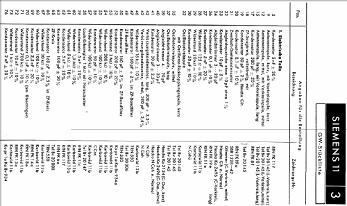
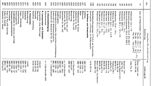
- Lange+Schenk+FS-Röhrenbestückung
- Weitere Modelle
-
Hier finden Sie 2514 Modelle, davon 2111 mit Bildern und 1325 mit Schaltbildern.
Alle gelisteten Radios usw. von Siemens (& Halske, -Schuckert Werke SSW, Electrogeräte); Berlin, München
Sammlungen
Das Modell befindet sich in den Sammlungen folgender Mitglieder.
Forumsbeiträge zum Modell: Siemens & Halske, -: 11GW
Threads: 3 | Posts: 4
I have run the 11GW on 115V and 220V. Now that restoration is finished, I left it in the my local 115V mains setting, because it draws less power/heat.
One interesting bit about this radio is that the B+ voltage follows the mains directly, so it is twice with 220V operation. The ballast resistor is used only for the heaters. I did notice somewhat more sensitivity/gain with 220V.
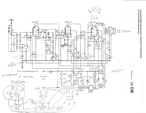
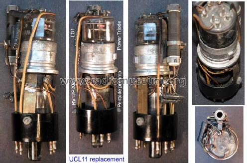
The RV12P2000/LD1 audio module replacement for the UCL11 works well in either setting because the grid bias also follows the B+, but the 220V setting delivers higher power before clipping at the preamp input.
I downloaded two different versions of the 11GW schematic from RMORG. The older version modified with the audio module, is at d_siemens_11gw_audio_module.pdf The later version d_siemens_11gw_sch.pdf shows separate negative terminals for the two supply bypass caps. This is a very important difference for hum injection into the power tube grid bias.
Having two separate electrolytic caps eliminates the need for the low voltage electrolytic bypass at the power tube cathode, and also makes it possible for the combination preamp/output tube to share the cathode at ground potential. The current drop is obtained from the current flowing between the two electrolytic negative legs, which still has the hum of the first cap.
In the original wiring, both electroytics returned to ground, the bias was obtained from unfiltered B- pulsating current. On first inspection, it would seem that this could not work at all, given that the pulsating current was zero most of the time, and produced -20V negative peaks accross the 125 Ohm bias resistor.
But the large 700k grid bias resistor and 10nF grid coupling cap formed a 2Hz low pass filter to filter the pulsating -20V into a ripply -5V. So the stage coupling cap serves two purposes in this circuit. The remainder of the hum clean up was done with negative feedback from transformer output to the bottom of the volume control. The feedback network is a wein bridge type of RC-CR network with a resonance around 15Hz, for maximum feedback at this frequency.
If the negative feedback lowered gain by 4x at 60Hz, that would mean a 4x reduction in hum for a given level of output. I would guess that if negative feedback is used there it should drop the gain by at least 2x, and probably 4x, otherwise there is not much point in NFB. ( I did not measure how much NFB dropped the gain)
The negative feedback is reduced at higher volume levels or for very weak stations as the volume pot is cranked up but is not eliminated.
My 11GW came wired as an early version with common negative bypass cap terminals. Separating the negative terminals of the electrolytics as shown in the later schematic, improved hum further. In my restoration, I splurged a bit and added a 1000uF bypass accross the 125 Ohm negative bias resistor because I wanted to clean up the ripple for use of this negative bias source with the preamp stage. I think I kept the spirit of the audio module design of gently improving the radio.
It appears that the economics of electrolytic caps ultimatelly resulted in two capacitor bodies in later desings: One low voltage cap for the cathode bypass, and two high voltage caps in the same can for B+. This solution should cost about the same as the solution in this radio, but having a total of three caps in two cans produced the least hum.
Comments invited,
-Joe Sousa
Joe Sousa, 26.Oct.08
This schematic for the 11GW d_siemens_11gw_audio_module.pdf includes the internal schematic of a home made audio module replacement for the UCL11 triode/pentode. The module includes a LD1 power triode and a RV12P2000 pentode preamp wire as a triode. The module also includes a 350 Ohm power resistor to soak up 40V of heater power and leave 12V for each of the tubes in the module. Each tube in the module also has a shunt resistor at the heater for fine adjustment of 100mA and 75mA heater currents for the LD1 and RV12P2000 tubes respectivelly. A 250 Ohm resistance biases the cathode of the power triode, but without electrolytic bypass.
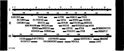
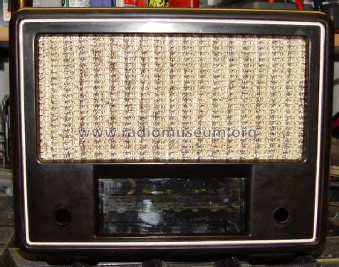
The original dial glass was broken. A replacement dial glass was made with a laser printout on acetate transparency, and sandwiched between two pieces of clear glass.
I added a 1meg bias resistor from the neg bias supply to the first audio stage because it would clip on loud passages. It sounds very nice now.
Comments invited,
-Joe Sousa
Joe Sousa, 26.Oct.08
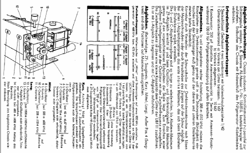
Bei diesem Modell ist bei den Schaltplänen eine Kopie der Skala vorhanden, falls durch ein Missgeschick mal eine Skala unbrauchbar wird oder schon war.
Die Skala ist zu Anschauungszwecken grösser als das Original hochgeladen und muss für die Verwendung auf 128 x 52,5 mm verkleinert werden.
Grüsse
Peter Steffen
Peter Steffen, 14.Jun.07