- Hersteller / Marke
- Telefunken Deutschland (TFK), (Gesellschaft für drahtlose Telegraphie Telefunken mbH
- Jahr
- 1939/1940
- Kategorie
- Autoradio, evtl. kombiniert mit Tonspeichergerät
- Radiomuseum.org ID
- 4241


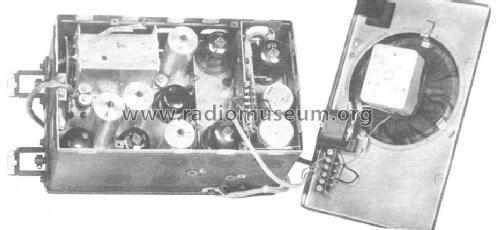
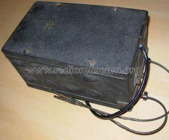
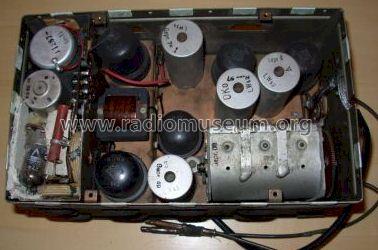
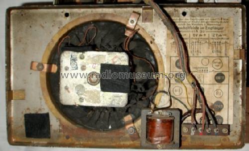
Innenansicht

EbayDE Item: 4629108985 user hu jarot
EbayDE Item: 4629108985 user hu jarot
EbayDE Item: 4629108985 user hu jarot
EbayDE Item: 4629108985 user hu jarot

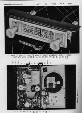
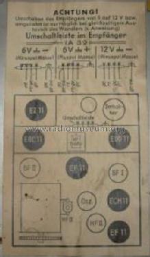
Quelle Rundfunkgrosshandels 1939-40
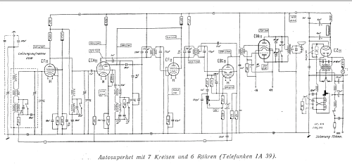
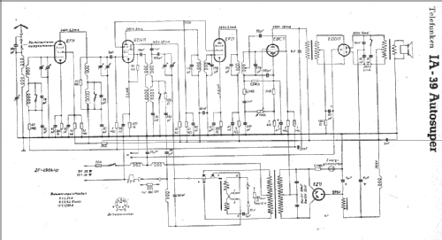
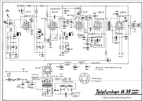
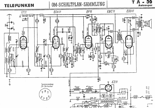
Klicken Sie auf den Schaltplanausschnitt, um diesen kostenlos als Dokument anzufordern.
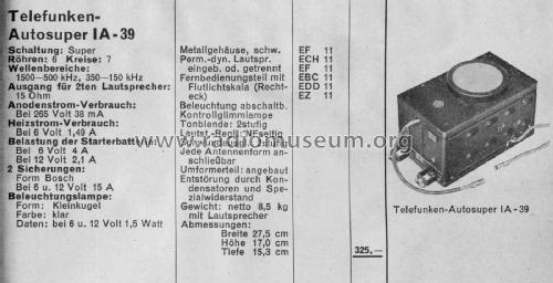
- Anzahl Röhren
- 6
- Hauptprinzip
- Super mit HF-Vorstufe; ZF/IF 490 kHz
- Anzahl Kreise
- 7 Kreis(e) AM
- Wellenbereiche
- Langwelle, Mittelwelle (LW+MW).
- Betriebsart / Volt
- AKKU-Speisung (für alles, z.B. bei Autoradios und Amateurgeräten) / 6/12 Volt
- Lautsprecher
- Dynamischer LS, keine Erregerspule (permanentdynamisch)
- Material
- Metallausführung
- von Radiomuseum.org
- Modell: IA39 - Telefunken Deutschland TFK,
- Abmessungen (BHT)
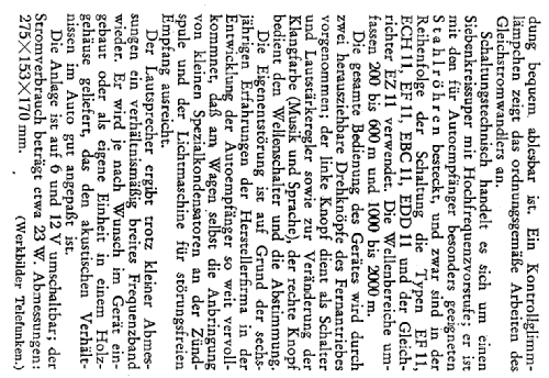
- 275 x 170 x 154 mm / 10.8 x 6.7 x 6.1 inch
- Bemerkung
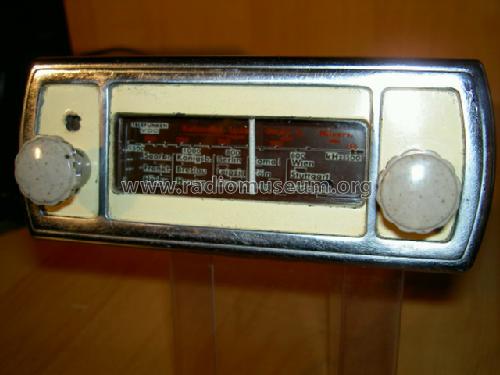
- Bedienteil mit 2 biegsamen Wellen von VDO. Deshalb VDO-Telefunken auf der Skala. Zweitlautsprecherausgang.
- Nettogewicht
- 8.5 kg / 18 lb 11.6 oz (18.722 lb)
- Originalpreis
- 325.00 RM
- Datenherkunft
- Handbuch WDRG 1939 / Radiokatalog Band 1, Ernst Erb
- Schaltungsnachweis
- Lange+Schenk+FS-Röhrenbestückung
- Weitere Modelle
-
Hier finden Sie 3580 Modelle, davon 3167 mit Bildern und 2126 mit Schaltbildern.
Alle gelisteten Radios usw. von Telefunken Deutschland (TFK), (Gesellschaft für drahtlose Telegraphie Telefunken mbH
Forumsbeiträge zum Modell: Telefunken: IA39
Threads: 1 | Posts: 1
For those who like to repair the famous early-age car radio made by Telefunken, IA39, here are some tips which I found useful:
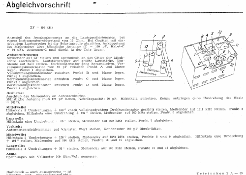
1. IF transformers - the capacity is 200pF, not 175pF, as shown in the diagram taken from the Empfanger Schaltungen part IX. The condensers were wrong, so after careful selection of precise 200pF, I put new ones under the aluminium shield (ee the picture).
2. Small pF condesers HOGER glued in the ceramic cover were almost wrong, this is the well known problem of Telefunken sets made during 1939/40. Have to be changed.
3. Do not move the tuning ferrite cores - the danger of damage, they are very small and a special tool is needed to turn them. In my set, all coils were tuned well.
Some pictures showing details of electrical construction follow.
Regards, Viktor
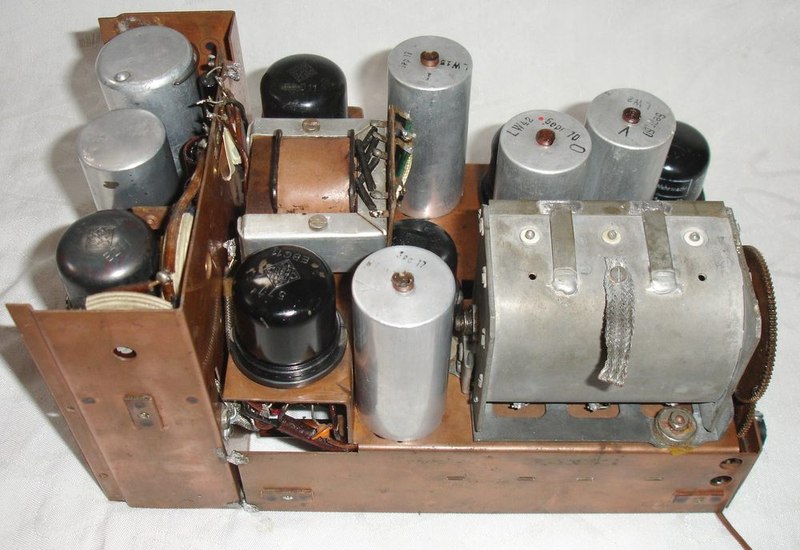
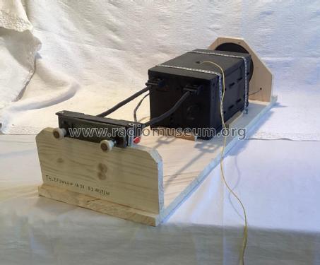
Overall view on the construction - the output transformer is not original one.

The tuning wheels - lubricate to make smooth operation.

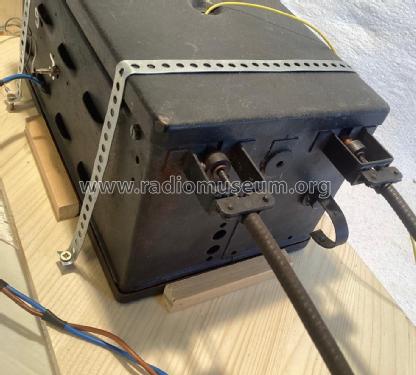
The view on the DC/DC changer.

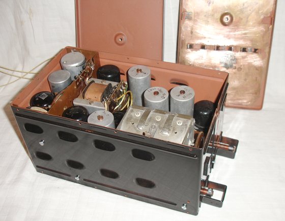
The layout of electrical components - the two upper condensers located near switch are changed.

IF coils - A: original condesers, damaged - B: replacement by proper ones.
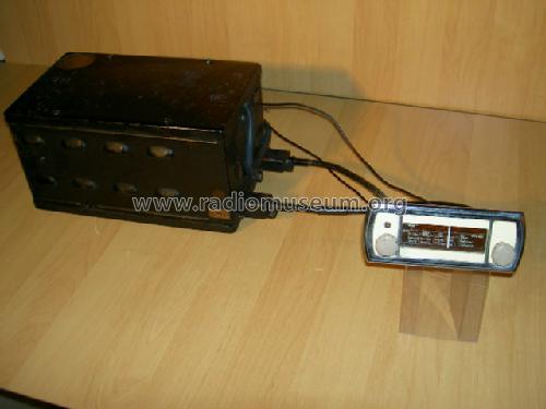
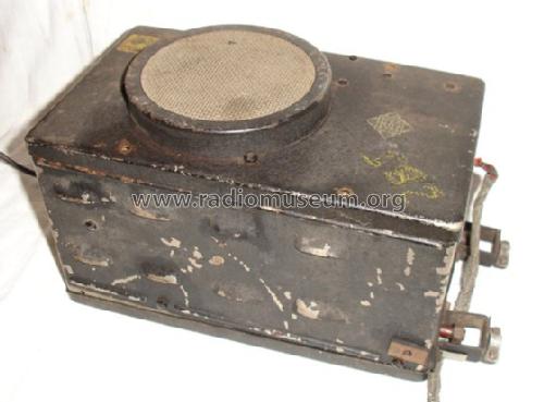
Finalisation of restoration.
The box has been cleaned and painted by a black color. This set is a little bit modified, the output transformer is mounted into the radio. In the original description, the laudspeaker and the output transformer are attached on the to cover. Pictures from the original radio are at the end of this article.

The "not touched" receiver


Viktor Cingel, 31.May.09