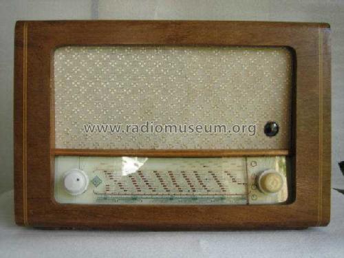
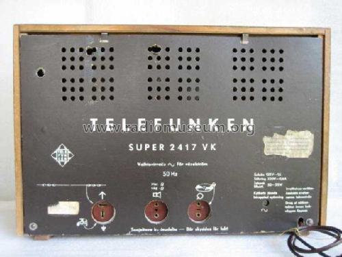
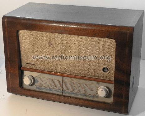
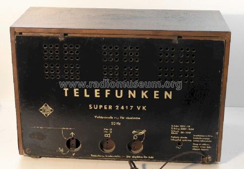
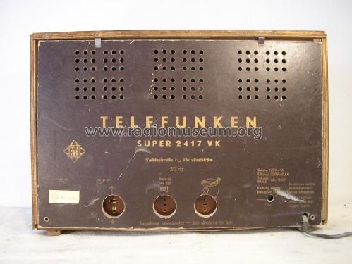
Super 2417VK
Telefunken, Helsinki
- Country
- Finland
- Manufacturer / Brand
- Telefunken, Helsinki
- Year
- 1949 ?
- Category
- Broadcast Receiver - or past WW2 Tuner
- Radiomuseum.org ID
- 98083
1/3
2/3

3/3


Radio 2/1949


- Number of Tubes
- 6
- Main principle
- Superheterodyne (common)
- Tuned circuits
- 5 AM circuit(s)
- Wave bands
- Broadcast, Long Wave and Short Wave.
- Power type and voltage
- Alternating Current supply (AC) / 110-240 Volt
- Loudspeaker
- Permanent Magnet Dynamic (PDyn) Loudspeaker (moving coil) / Ø 18 cm = 7.1 inch
- Material
- Wooden case
- from Radiomuseum.org
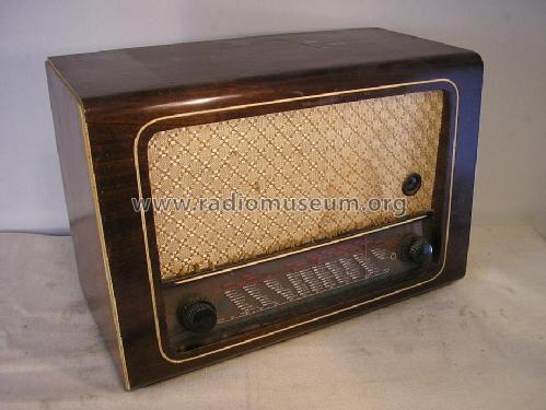
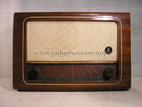
- Model: Super 2417VK - Telefunken, Helsinki
- Shape
- Tablemodel, low profile (big size).
- Dimensions (WHD)
- 530 x 363 x 262 mm / 20.9 x 14.3 x 10.3 inch
- Net weight (2.2 lb = 1 kg)
- 11 kg / 24 lb 3.7 oz (24.229 lb)
- Source of data
- - - Data from my own collection
- Author
- Model page created by Eero Ukkola. See "Data change" for further contributors.
- Other Models
-
Here you find 21 models, 20 with images and 2 with schematics for wireless sets etc. In French: TSF for Télégraphie sans fil.
All listed radios etc. from Telefunken, Helsinki
Collections
The model Super is part of the collections of the following members.
Forum contributions about this model: Telefunken, Helsinki: Super 2417VK
Threads: 2 | Posts: 2
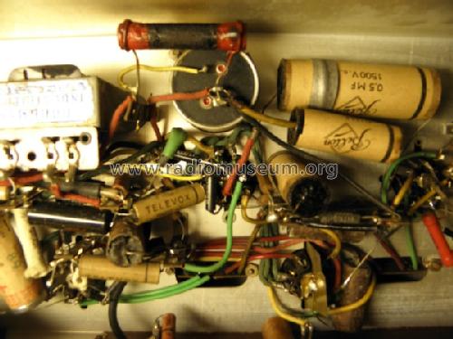
A couple of nights ago replaced some of the paper caps by Italian-made ICEL capacitors I bought from a local vendor here in Helsinki. Can't stop wondering at how much smaller the capacitors are nowadays than they were 60+ years ago.
Today I received a nice pair of EBL21 from a friendly seller in the Netherlands (one tube will go to the set of spare parts for this radio). Replaced the AF output tube, and got more signs of life. The AF responds nicely, the volume control is apparently good. Judging by the noice coming from the speaker, I will have to thoroughly clean the sockets, though. Other than that, the project seems to be going well.
Dimitri Vorobiev, 01.Mar.12
I got this radio from a flea market in Porvoo where it was sitting in a corner with a really attractive price tag. Previous owner wrote on the price tag that the light was working, and there was some noise coming out. Apart from missing tuning and band switching knobs, there were no apparent problems with this radio, so I decided to take it home for a restoration project.
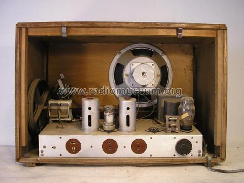
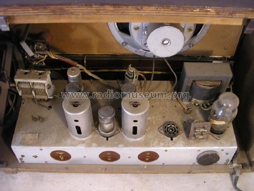
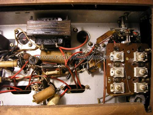
The condition of the internals was surprisingly good. There was very little dust (apparently, it comes from a clean home). Mechanically, the chassis looks intact. There are traces of previous soldering work in the circuits, and I should say that whoever did that work did it well.
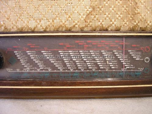
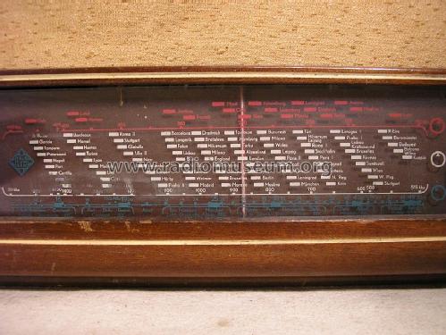
First, I took the chassis out of the wooden cabinet, unmounted the dial glass, and cleaned up the white cardboard behind the latter. Also, both dial lapms were blown, and I had to replace them. These common 6.3V E10-based lamps, and I had such in my stash. Paint on the dial glass is fragile and started to detach and fall off in tiny pieces.
The output tube (EBL21) is ruined, but still amplifies. My theory is that a leaking coupling capacitor killed it. The structures inside the tube are physically bent, and there are loose flakes of what seems to be burnt getter inside the bulb. Still, the AF part was somehow working, as I heard hum when touching the grammophone input.
The magic eye was barely visible, apparently very little emission left in it. EM4 are expensive, so I am thinking of replacing it with Soviet 6E5C at some point.
Yesterday I started recapping the radio. I plan to replace the electrolytics as well as paper capacitors first, change the resistor in the B+ filter circuit, then try the radio with NOS output and AF preamp tubes. When the AF part is OK, it'll be time for the RF part. I also plan to use this forum for my notes on restoration.
Dimitri Vorobiev, 15.Feb.12