SG3 kit for LW & MW
Unknown - CUSTOM BUILT: GB
- Produttore / Marca
- Unknown - CUSTOM BUILT: GB
- Anno
- 1931 ?
- Categoria
- Kit, scatola di montaggio (parti sfuse e istruzioni o solo istruzioni di montaggio)
- Radiomuseum.org ID
- 240640
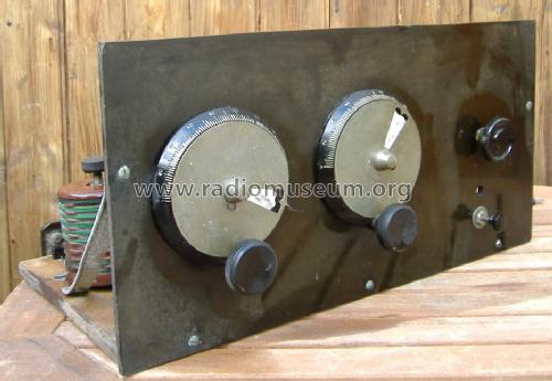
Simply wiped. Before restoration
Ebay about 2011

V3 is wrong, marked with red X.
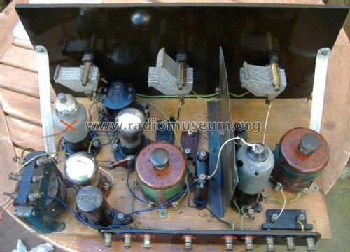
V3 is incorrect type (marked with red X)

Clicca sulla miniatura dello schema per richiederlo come documento gratuito.
- Numero di tubi
- 3
- Principio generale
- A reazione (con rigenerazione); 1 Stadi BF
- N. di circuiti accordati
- 2 Circuiti Mod. Amp. (AM)
- Gamme d'onda
- Onde medie (OM) e onde lunghe (OL).
- Tensioni di funzionamento
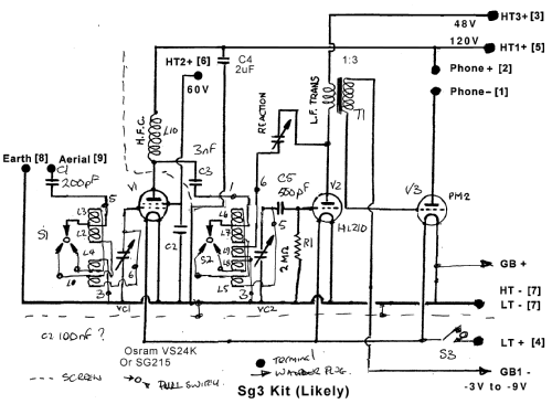
- Batterie (di accumulatori e/o a secco) / 2 & 9 & 60 & 120 Volt
- Altoparlante
- - Questo apparecchio richiede altoparlante/i esterno/i.
- Radiomuseum.org
- Modello: SG3 kit for LW & MW - Unknown - CUSTOM BUILT: GB
- Forma
- Soprammobile a cassapanca o cassetta, solitamente con coperchio (NON a leggio)
- Dimensioni (LxAxP)
- 395 x 200 x 270 mm / 15.6 x 7.9 x 10.6 inch
- Annotazioni
-
Wooden base board with copper foil on underside and Paxolin or Ebonite front panel. Can fit a box with lid. Depth includes knobs and terminals.
Wavechange by push-pull switches on both coils, or terminals to front panel switches, separate slow motion tuning for each stage.
Capacitor Regeneration control and push-pull on-off on LT feed ("A" accumulator supply).
External high impedance headphones, horn or read speaker.
A number of almost identical layout three valve MW/LW kits using 2V or 4V 4 pin valves. Screen Grid RF, Triode Regeneration/Detector and transformer coupledTriode audio Amp. Standard ready made cabinet was available. The September 1933 Popular Wireless "Northern Star" is a later varation of this basic design.
As there is a separate tapped 9V Grid bias and tapped HT battery almost any selection of 2V, 4V or 6V tubes can be used with B4 base for "Screen Grid", RF or AF preamp or Detector Triode, and output using AF preamp (Phones only) or Audio output Triode for Reed Speaker or Moving coil with transformer.
- Autore
- Modello inviato da Michael Watterson. Utilizzare "Proponi modifica" per inviare ulteriori dati.
- Altri modelli
-
In questo link sono elencati 118 modelli, di cui 108 con immagini e 10 con schemi.
Elenco delle radio e altri apparecchi della Unknown - CUSTOM BUILT: GB
Collezioni
Il modello SG3 kit for LW & MW fa parte delle collezioni dei seguenti membri.
Discussioni nel forum su questo modello: Unknown - CUSTOM: SG3 kit for LW & MW
Argomenti: 3 | Articoli: 3
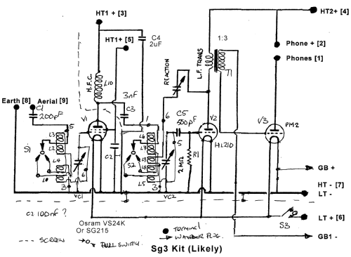
Probably the design was originally three tubes, the base board hardly fits four and one transformer and socket seems later type.
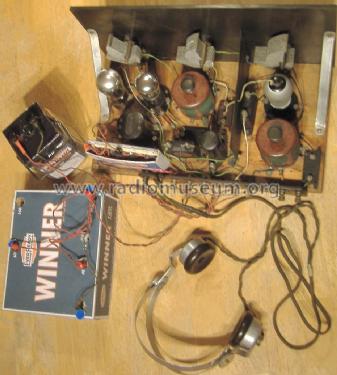
So wired as a three valve (tube) kit Radio. Osram VS24K as RF "SG" Tetrode, HL210 Triode as Regenerative amp and detector, Mullard PM2 Triode as output. VS24K g2 volts is 60, all other HT is 120V. The PM2 has -9V grid bias. The "Ever Ready Sky Queen" box behind is a spare (no radio or amp in it!) with a 240V to 6V transformer (as an audio transformer) driving a 1950s 4 Ohm moving coil loudspeaker (2n2F snubber/tone correction on primary). There is no amplification in it. It's instead of 4K headphones,
Video Demo using extension telephone bell with a floppy paper cone as a 3600 Ohm "reed armature" speaker.
I have no high impedance phones, so I used a transformer and moving coil speaker for a longer video demo after dark (no daytime MW here in Limerick, Ireland).
Michael Watterson, 09.Sep.13
The coils wave change switches were seized. As well as fixing the switches I worked out the wiring and measured the inductances in MW & LW mode. This shows the coils and switches are working and the wiring is actually correct.
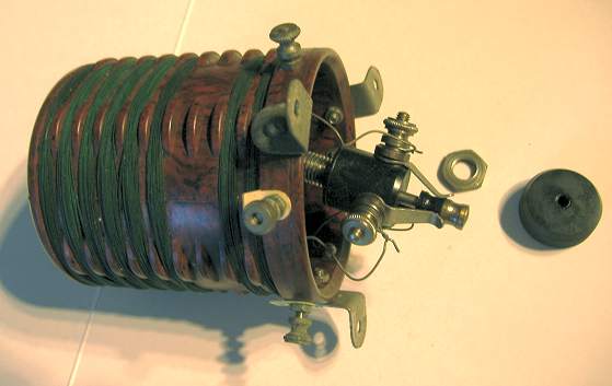
Information on the coils is below the photos. Heat from gas stove and hammering was needed to free the switch shaft in the "collet" / outer barrel on both.
The first RF stage (V1, the RF SG/Tetrode S210_Tungsram or possibly an SG215) has 8 windings and the second RF stage has an additional pair of windings for "tickler", the coil connected to anode via a capacitor for regenerative feedback on V2, HL210 (triode recommended for Detector or LF preamp).
RF Coil unit 1
Three connections are labelled 3, 5 & 6. Functions according to existing wiring:
Common / 0V / HT- / LT- / Earth : 3
Tuning capacitor / grid : 6
Aerial via capacitor : 5
I have arbitrarily referred to unused connection between 3 & 5 as 2 and beside 6 as 4.
Pulling up the switch is MW and shorts 2 , 4 & 5, pushing down is LW. The unlabelled connections I have called 2 & 4 are obviously for front panel Wavechange switching along with 5 which is aerial input via a capacitor.
Inductances after switch repair.
| Term | LW | MW |
|---|---|---|
| 3 - 5 | 1mH | 51uH |
| 3 - 6 | 2.9mH | 148uH |
| 5 - 6 | 1mH | 50uH |
| 6 - 4 | 54uH | 49uH |
| 3 - 2 | 57uH | 51uH |
| 2 - 4 | 2.5mH | 1uH |
Coil layout on former.
The top 6 windings connect a top to 2 and bottom to 4, the centre tap is 5. There is then a gap of two "windings" and the next coil is on 2 and 3. The last coil is 4 & 6. The connections in bold have two winding connections.
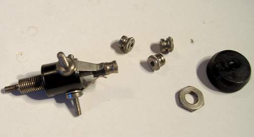
Repair of switches


Now we can heat and hammer the innner shaft in outer barrel to free it.
Overnight soak in WD40 didn't work!


RF Coil unit 2
Four connections are labelled 3, 4, 5 & 6. Functions according to existing wiring:
Common / 0V / HT- / LT- / Earth : 3
Tuning capacitor / grid via capacitor : 5
Input from V1 anode via capacitor : 1
Feedback regeneration to V2 anode via Regeneration variable capacitor : 6
I have arbitrarily referred to unused connection between 5 & 6 as 4 (beside 5) & 2 (beside 6).
Pulling up the switch is MW and shorts 2 , 4 & 1, pushing down is LW. The unlabelled connections I have called 2 & 4 are obviously for front panel Wavechange switching along with 1 which is input via a capacitor.
Inductances after switch repair.
| Term | LW | MW |
|---|---|---|
| 1 - 3 | 1mH | 60uH |
| 1 - 5 | 1mH | 55uH |
| 3 - 5 | 3mH | 165uH |
| 1 - 6 | 1mH | 178uH |
| 5 - 6 | 3.5mH | 338uH |
| 6 - 3 | 119uH | 1uH |

Conclusion
The tricky bit was fixing/freeing the wavechange switches. Thanks to those folk that suggested the wavechange switches likely built in.
Aluminium (or copper, brass etc) screening cans would be very large as ideally the can wall should be spaced a radius out from edge of coil!
The wire appears to be solid single strand rather than "Litz" and cotton covered, cheapskates! Lovely Bakelite formers. The layout isn't what I would have thought of! No wonder the Mullard "Wireless for the million" magazines usually show a simplified coil and note that wave band switching is omitted for simplicity of understanding the circuit.
Reverse Engineering
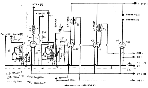
With the coils "mapped" out a schematic is possible. So I have uploaded a sketch of it, I added missing earth on the C2 & C4 (large paper capacitors), swapped the side of HFC L10 that C4 was connected to and connected C3 to V1 anode. That was the three missing wires and one wiring error.
Unfortunately the Primaries on both "inter-stage" audio transformers are open circuit. These are very fragile and could have been burnt out by lack of grid bias. V2 HL210 "grid leak" resistor R1 is intermittantly 6M Ohm to open circuit (> 20 M Ohm), it's usually about 2M ohms.
Michael Watterson, 05.Sep.13
Initial Impressions before delivery
I doubt it's 1920s, though a 1920s style of panel, such panels are common on Kit radio 1931 to 1933. The RF input is likely a SG215 style and the audio out looks to be a 4 pin base Pentode as it has a top cap. The driver can be read as a PM2. The other valve can't be read but is similar appearance (no top cap).
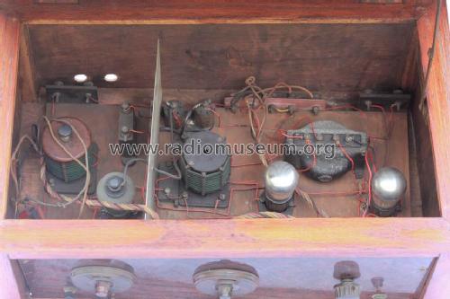
The original ebay photos of my unknown TRF (kit?)

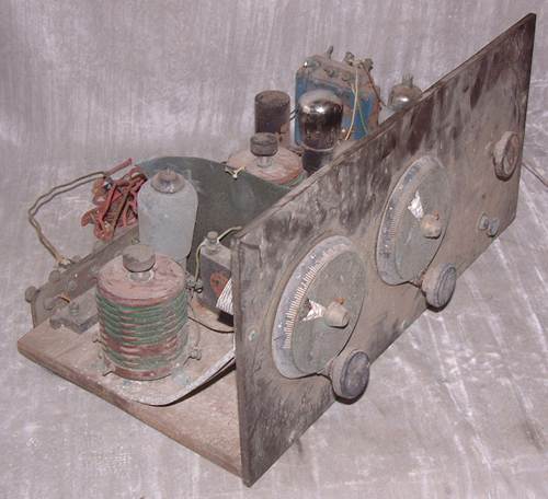

The blue item far left is a transformer. Aerial & Earth are two nearest connections.
The two tuning dials are similar to those on 1928 Mullard kits. The third variable capacitor is likely "reaction"? There is a third large transformer, possibly for a low impedance moving coil speaker as a reed type doesn't need a transformer. That also suggests 1932 /1933, earlier would be reed not moving coil usually.
April 1931 "Radio for the Million" has Pentode PM22 as an option instead of Triode for output on the "Conversion 4" and a SG PM12 for both RF stages. The driver is PM2DX. It's not really similar. That issue still promotes "reed" speakers.
For now we can only guess. But it's more like a "Magazine Kit" than a Mullard or Lissen I think and valves (tubes) and Loudspeaker arrangement too "late" for 1920s.
Probably I spent too much (€31.44 and about €19 shipping) for a really poor (wreck) 1930s kit TRF, but it will give some fun restoring it.
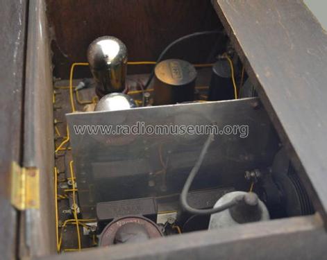
The reality after unpacking and a quick clean
I did take a lot of photos before even I cleaned it and also after simple brush and wipe but before any restoration.
Just a quick wipe, honest, no restoration!
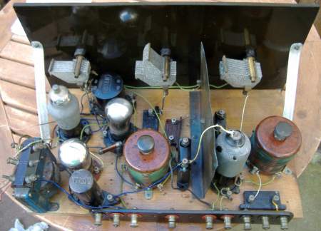

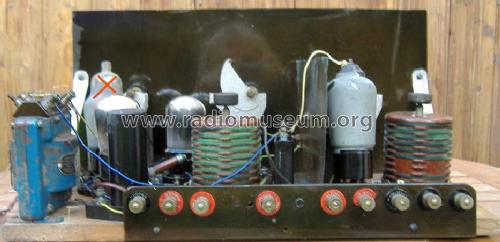
Valves/Tubes in order
Tungsram S210: A SG for tuned RF stage. First large coil, and a large choke for anode load near phone connections.
Mullard HL210: Triode, Tuned Detector and Regeneration (capacitive adjustment). Anode also connects to 1st interstage transformer. which feeds 3rd socket.
Third socket has pin 1 to large blue transformer. It has an Osram VS24K, not a pentode. This is a SG valve and there is no top cap wire. It's obviously the wrong valve.
Last socket is a Mullard PM2, its grid is fed from the big blue transformer and its anode connects to a terminal marked "Phones"
So I made a mistake, what I thought was a Pentode and output transformer was a SG (incorrectly fitted) with inter valve transformer and the other "transformer" is an RF choke for SG (V1) anode supply.
What is it?
It's a late 1920s kit, 1 x SG and 3 x triodes, a common type of TRF with Regeneration. One valve is incorrect. A few wires are missing, but obvious where they should be. Though some companies and magazines publishing this kind of kit up to 1934. A mix of brands suggests a "home brew" rather than complete set of parts (two brands of mica caps, two brands of transformers).
Coils
The coils do have push-pull wave switches but they are siezed. It was easy to remove the switch on one coil, but extremely difficult to free the switch shaft. One switch is now working.
Capacitors.
The two large paper capacitors are so leaky it shows on DMM Ohms range. The base is sealed with wax and card. It's easy to leave it intact internally but with wires snipped and fit a modern capacitor inside too. The others must be Mica, they are fine.
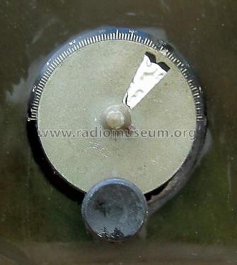
Slow motion Drives
These do work, but a white plastic disc is crumpled up. It's blank!

Drive comes apart relatively easily.
There is a thick rubbery pad between the fixed scale and the panel.
What is the white disc and associated window for? The rotating metal disc has a pointer to the outer log scale. The spring and washer load the knob on the edge of the metal disc for the geared drive.
Next is to "reverse" engineer what is connected. Either it was never finished or someone started to change it. The coil connections don't seem quite right! All the grid bias connections seem to be missing except the grid leak resistor on "V2" HL210
Michael Watterson, 05.Sep.13