
TDA7040T

|
|
||||||||||||||||||||||||||||||

|
Hits: 4785 Replies: 1
TDA7040 usage
|
|
|
Michael Watterson
17.Aug.16 |
1
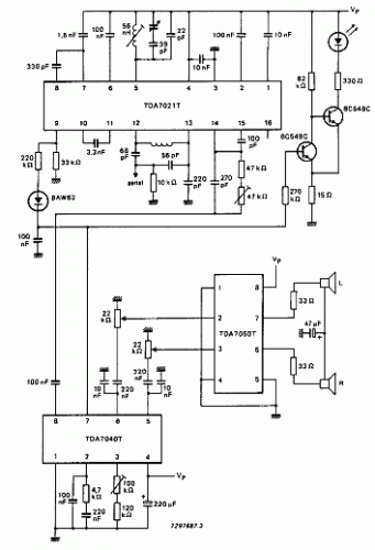
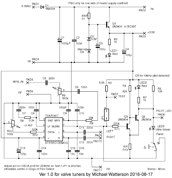
The application notes/data sheet show the TDA7040T used in a three IC pocket battery portable. The pin 7 has actually three functions: Stereo / mono blend. A short is Mono. More than 200K or so seems to be full stereo. Test VCO out, 224kHz for alignment. You don't really need this if you have a stereo signal. Pull pin to +Vs via 5.6K ohms Pilot indication of 19kHz. The example is for low power battery, so the LED acts more as an "out of tune" indication and goes out on reception of stereo! The schematic shows how a regular panel LED may be driven with input attenuation and power supply for a suitable valve (Tube) FM tuner. The input pot is driven from BEFORE the de-emphasis R & C, either from discriminator or via a unity gain buffer.
A low drop out 5V regulator or single chip 3.3V part can be used. However the Pilot LED drive works because the ultra efficient green LED for panel is about 2.4V and the red LED (on strip board to aid alignment) is about 1.3V to 1.6V. Thus with a 3.5V supply only one or the other is on. Possibly! I've simply not tested to see if the LED drive works at 5V. A single transistor would seem to be the solution to drive the LED normally, but to avoid loading pin 7 and activating "blending to mono" you would need a Darlington transistor pair. |
|
Michael Watterson
17.Aug.16 |
2
The construction doesn't need a PCB. Even tag strips are possible. Use a DIL adaptor PCB for the SMD IC. Tin pads and reflow with a dry iron, even 4mm flat chisel tip 30W to 50W will work. Or use 0.6mm solder and hold chip in place with tiny blob of glue or "blutack". Early version with only LED that goes out for 19kHz detection. The input pot had to be a little below 50% signal level for a Dynaco tube FM tuner.
|

End of forum contributions about this tube
| Data Compliance | More Information |