
TDA7088T

|
|
|||||||||||||||||||||||||||||||||||||||||


")
|
Klicks: 3981 Antworten: 0
TDA7088T Low IF Trick
|
|
|
Michael Watterson
21.Jun.15 |
1
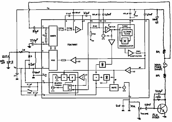
Complete FM radio using Asian equivalents of the TDA7088 are now still common (2015) for about €2 retail. This often includes stereo earbuds that can be as good as €10 earphones sold separately. Often to the battery is included ( 2 x AA or 2 X AAA or a Lithium CR2032 coin). How can it be so cheap? Even a Ceramic IF filter might cost as much as the Integrated circuit. The trick is to have an IF of about 75 KHz and use R C (resistor & capacitor) based Op-amp based bandpass filter. This is achieved by using the PLL synchronous detector as extreme AFC feedback, basically turning the superhet into a tracking filter. This has the effect of reducing the Wideband FM to simple phase modulation, at the most extreme feedback.
Centre top is the RC Op-amp based filter. Normally the 38KHz Stereo DSBSC L-R signal is of no concern, nor the 57KHz carrier 1187 bps RDS data. However it's possible to adjust the RC values and slightly raise the IF centre frequency so a Stereo Decoder IC and/or RDS decoder IC works better, though as 76kHz is the centre frequency, the default values often work, then feed RDS data to a PIC microcontroller and simple LCD display (I have done this including porting some existing RDS decoder software). With pure phase modulation the minum bandwidth is about 116KHz for RDS, certainly possible with 76KHz centre IF. Bottom right is feedback from synchronous demodulator to VCO, which uses an external varicap diode. The method of station scan and lock is also interesting. Often two transistors drive the earphones which are typically series anti-phase as they are standard 3 pole 3.5mm stereo type. The hand or pocket is capacitively coupled "earth" and the earphone cable is the aerial. The rather better FM radio in a smart-phone (usually with Stereo and RDS) uses the earphones as aerial in the same way. The USA has a similar system to European RDS, so alike that the same decoder IC / Software works. The USA though has a 2nd even higher data carrier, SCA, at 67kHz (nothing to do with HD Radio) I don't know if it can work with this system. Some stattions may have a second SCA carrier at 92kHz, that certainly can't work. US Stations transmitting "HD Radio" (in reality poor bit rate) can cease the SCA at 67KHz and 92KHz to get the best bitrate possible. It would be interesting to try and adapt this circuit as a front end to tune the HD radio subcarrier and then try decoding with a laptop, perhaps using a USB based ADC. |
Ende Forumsbeiträge zur Röhre
| Datenkonformität | Mehr Informationen |