
EF89

|
|
|||||||||||||||||||||||||||||||||||||||||


|
Hits: 6561 Replies: 0
EF89: Anatomy
|
|
|
Michael Watterson
18.Mar.12 |
1
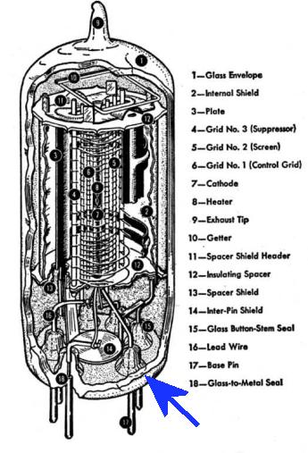
This is a "real" Pentode. That is to say it has three spiral wire electrodes called "grids" between the Cathode and the Anode (Plate). Most of the ECLxx, PCLxx and UCLxx and many DLxx, ELxx. PLxx and ULxx don't have a third grid spiral wire, but "beam forming" rods or plates. In some cases they are called that to avoid the Pentode Patents at the time (Philips). Kinkless Tetrode and Beam Tetrodes are essentially a kind of Pentode (usually output types as mentioned) that uses a pair of Anodes/Plates and an electrostatic lens instead of the g3 or Suppressor grid wire spiral. The Russian Rod Pentodes take this to an extreme. Often Heptodes use a pair of rods or plates for g2 which acts more like an intermediate anode. Classic RCA tube diagram
The g1 or Control Grid (Signal Grid) is a spiral of wire close to the Cathode to control the current flow using a voltage more negative than the cathode. The Electrons are more repelled but many pass through the gaps in the spiral wire. If the spiral varies in spacing a "variable cut off" type with good AGC but poorer large signal linearity is created. RF and IF amplifiers may have the variable spiral and Power output types the fixed pitch spiral. Eventually the voltage is so negative that no electrons can pass the grid wires, This is cut-off. No current flows. If the grid is positive at all then some electrons will be attracted to the wire and flow in the grid. Anode current will not rise much but the grid current will.
The g2 or Screen grid screens the Anode from the control grid g1 and Cathode. It reduces the Anode / Control grid capacitance which is magnified by Tube Gain (Miller Effect). This makes the tube stable as an RF amplifier and extends frequency response. It does perturb the electron flow because the g2 (screen) must be a high voltage. This is minimised by making the spiral wider turns (bigger gaps). The effect is called Partition noise and makes the Pentode noisier than a Triode. The EF86 is type with minimised noise, only a little more noise than a Triode. Perhaps the screening then is not so good, The EF89 replaces the EF80 and EF85 for RF & IF work, the EF86 is a low noise part for Audio Preamps. However when the Anode voltage drops much below the g2 voltage (usually fixed at 1/2 HT, HT or via a resistor to HT) there is a point where the Voltage / current curve is negative (a kink) due to secondary emission and electron flow to g2 increasing. A third "Suppression" or "Suppressor" grid, g3 is added with wider spiral between g2 and the Anode. This grid must be at the cathode potential, or below lowest Anode voltage. On output or low frequency types it might be wired to the Cathode. But on an RF amplifier it has to be wired to Zero Volts, or a voltage below lowest anode volts and at RF "earth" otherwise if there is signal on the Cathode the tube would oscillate. From the latter 1950s till the end of Valve Radio the EF89 was a popular IF Amplifier (Almost 6000 models listed in the Museum).
The EF89 Photo TourThe EF89 was damaged in transit by the ferrite rod coming loose. The Getter "flash" (black and Shiny) to remove last trace of air reacts with air and goes white.
We crack off the thin envelope glass. You can see the groove for the "getter"
That's not the Anode.
The Button base and pins cut off!
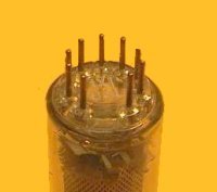
Connections to Electrodes at base (Shield bent back)
You can see the insulated Heater filaments in the Cathode tube at the middle
The button base is heated and crimped on to the pins.
The insulated "heater" pulls out of the cathode tube easily.
The top assembly is attached to the perforated screen/shield by 4 welds
Removal of top shield exposes all the electrodes Top black clip is Anode. Centre is empty Cathode tube (heater removed) Electrode support rods from Left to right along centre: g3, g2, g1, (Cathode), g1, g2, g3 Bottom black clip is Anode also
Take off the top Mica wafer.
Top view of electrodes after the Mica wafer is removed.
Bottom view
Take of the Shield/Screen
Now we can see the Anode (Plate). Really there are two, one on either side. The support rods constrict the electron flow to almost a pair of opposing beams. You can see why the two pairs of "beam forming plates or rods" and a pair of Anodes is a logical development to give the Kinkless or Beam Tetrode version of a Pentode.
We can see the anode is really two plates.
Side view of g1(control, signal grid) and Cathode tube. Note white Oxide coating to dramatically increase emission. A lot of tube development between 1935 and 1945 was making the control grid at higher precision, moving it closer to the cathode and using finer wire wound at a finer pitch. Many models have automated machine cut notches the grid wire is wound into and forced closed again.
The base end shield/Support The Perforated screen /shield tube is welded in two places to this.
The oxide coating (Barium Oxide mainly) is delicate and easily damaged!
Base end Mica Wafer
The End. I hope you found the tour interesting. Perhaps I should have shown and explained all the photographs in the reverse order to the taking of them, as that would be roughly the assembly order! For comparison below is the "Russian Rod Pentode". The next time I have a broken "Beam Tetrode" I'll photograph it to pieces... The Rod Pentode
Top view Russian Rod Pentode
The g1 or control grid is a pair of plates very close to the filamentary cathode.
Further ReadingLinks to some other Tube Articles (some also have other good links) |


End of forum contributions about this tube
| Data Compliance | More Information |