- Pays
- Allemagne
- Fabricant / Marque
- AEG (Radios) Allg.Elektricitäts-Ges.
- Année
- 1950/1951
- Catégorie
- Radio - ou tuner d'après la guerre 1939-45
- Radiomuseum.org ID
- 226
Cliquez sur la vignette du schéma pour le demander en tant que document gratuit.
- No. de tubes
- 4
- No. de transistors
- Semi-conducteurs
- 220E60
- Principe général
- Super hétérodyne (en général); FI/IF 473/20700 kHz
- Circuits accordés
- 6 Circuits MA (AM) 3 Circuits MF (FM)
- Gammes d'ondes
- PO, GO et FM
- Tension / type courant
- Appareil tous courants (CA / CC) / 110; 127; 220 Volt
- Haut-parleur
- HP dynamique à aimant permanent + bobine mobile / Ø 18 cm = 7.1 inch
- Puissance de sortie
- 4 W (qualité inconnue)
- Matière
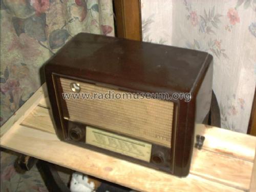
- Boitier en bakélite
- De Radiomuseum.org
- Modèle: 40GWU - AEG Radios Allg.Elektricitäts-
- Forme
- Modèle de table profil bas (grand modèle).
- Dimensions (LHP)
- 400 x 270 x 200 mm / 15.7 x 10.6 x 7.9 inch
- Remarques
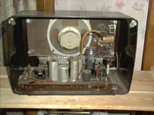
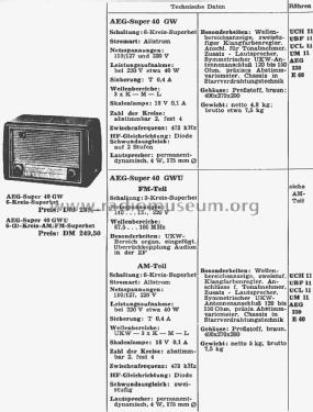
- Wellenbereichsanzeige. Zweistufiger Klangfarbenregler. Anschlüsse für Tonabnehmer und 2. Lautsprecher. Symmetrischer UKW-Antennenanschluß 120 - 150 Ohm. Chassis in Starrverdrahtungstechnik. Netzgleichrichter AEG 220/E60. Skalenlampe 18 Volt / 0,1 Amp. Wellenbereiche im VERG-Katalog fälschlicher Weise mit LW, MW, 3× KW und UKW angegeben.
- Poids net
- 5 kg / 11 lb 0.2 oz (11.013 lb)
- Prix de mise sur le marché
- 250.00 DM
- Source
- Kat.d. Rundf.Gr.Handel 1950/51 / Radiokatalog Band 1, Ernst Erb
- Source du schéma
- Lange Schaltungen der Funkindustrie, Buch 1
- Littérature
- Funkgeschichte der GFGF (8222)
- D'autres Modèles
-
Vous pourrez trouver sous ce lien 847 modèles d'appareils, 737 avec des images et 421 avec des schémas.
Tous les appareils de AEG (Radios) Allg.Elektricitäts-Ges.
Contributions du forum pour ce modèle: AEG Radios Allg.: 40GWU
Discussions: 1 | Publications: 1
Auf UKW Flankensuper, KEINE zweite UBF 11. Gerät hat nur einen KW - Bereich, nicht mehrere.
Reinhard Bittner, 25.Jul.03


