- Country
- Germany
- Manufacturer / Brand
- AEG (Radios) Allg.Elektricitäts-Ges.
- Year
- 1950/1951
- Category
- Broadcast Receiver - or past WW2 Tuner
- Radiomuseum.org ID
- 226

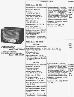
Q: Katalog RF-Großhandel 1950/51
Click on the schematic thumbnail to request the schematic as a free document.
- Number of Tubes
- 4
- Number of Transistors
- Semiconductors
- 220E60
- Main principle
- Superheterodyne (common); ZF/IF 473/20700 kHz
- Tuned circuits
- 6 AM circuit(s) 3 FM circuit(s)
- Wave bands
- Broadcast, Long Wave and FM or UHF.
- Power type and voltage
- AC/DC-set / 110; 127; 220 Volt
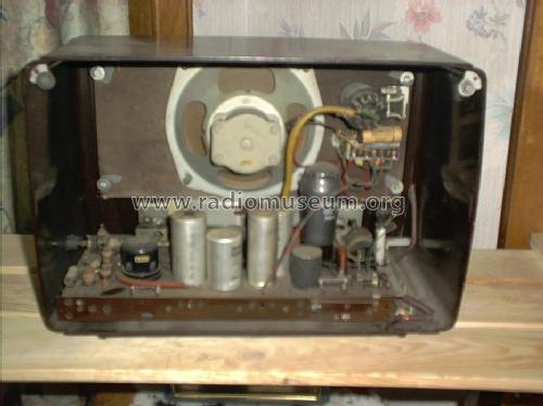
- Loudspeaker
- Permanent Magnet Dynamic (PDyn) Loudspeaker (moving coil) / Ø 18 cm = 7.1 inch
- Power out
- 4 W (unknown quality)
- Material
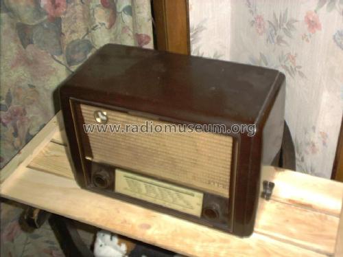
- Bakelite case
- from Radiomuseum.org
- Model: 40GWU - AEG Radios Allg.Elektricitäts-
- Shape
- Tablemodel, low profile (big size).
- Dimensions (WHD)
- 400 x 270 x 200 mm / 15.7 x 10.6 x 7.9 inch
- Notes
- Wellenbereichsanzeige. Zweistufiger Klangfarbenregler. Anschlüsse für Tonabnehmer und 2. Lautsprecher. Symmetrischer UKW-Antennenanschluß 120 - 150 Ohm. Chassis in Starrverdrahtungstechnik. Netzgleichrichter AEG 220/E60. Skalenlampe 18 Volt / 0,1 Amp. Wellenbereiche im VERG-Katalog fälschlicher Weise mit LW, MW, 3× KW und UKW angegeben.
- Net weight (2.2 lb = 1 kg)
- 5 kg / 11 lb 0.2 oz (11.013 lb)
- Price in first year of sale
- 250.00 DM
- Source of data
- Kat.d. Rundf.Gr.Handel 1950/51 / Radiokatalog Band 1, Ernst Erb
- Circuit diagram reference
- Lange Schaltungen der Funkindustrie, Buch 1
- Mentioned in
- Funkgeschichte der GFGF (8222)
- Other Models
-
Here you find 847 models, 737 with images and 421 with schematics for wireless sets etc. In French: TSF for Télégraphie sans fil.
All listed radios etc. from AEG (Radios) Allg.Elektricitäts-Ges.
Forum contributions about this model: AEG Radios Allg.: 40GWU
Threads: 1 | Posts: 1
Auf UKW Flankensuper, KEINE zweite UBF 11. Gerät hat nur einen KW - Bereich, nicht mehrere.
Reinhard Bittner, 25.Jul.03