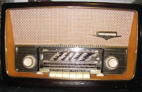
Rekord-Senior 60 Export
Emud, Ernst Mästling; Ulm
- Country
- Germany
- Manufacturer / Brand
- Emud, Ernst Mästling; Ulm
- Year
- 1959/1960
- Category
- Broadcast Receiver - or past WW2 Tuner
- Radiomuseum.org ID
- 132433

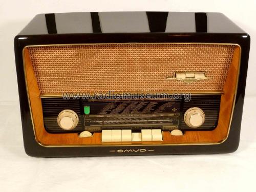
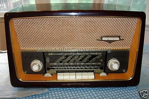
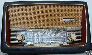
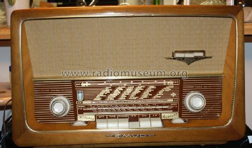
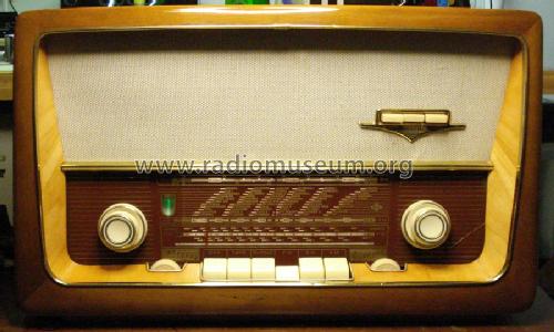
Front View
Back View

eBay seller castnowfishing
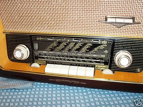
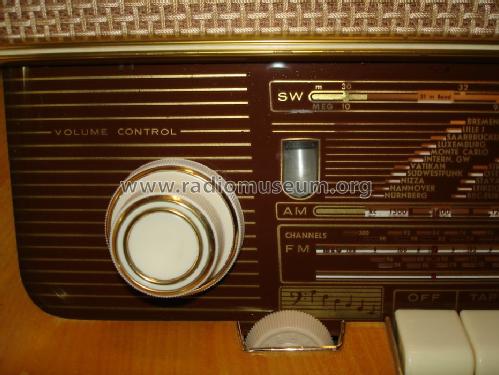
Dial Glass-Front
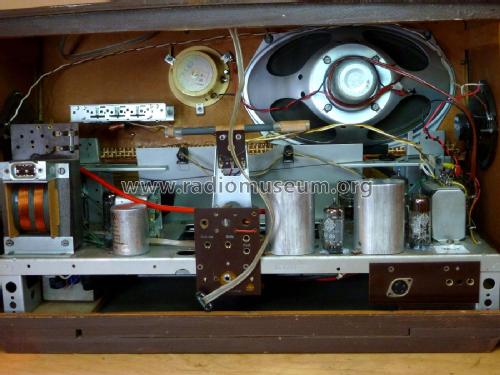
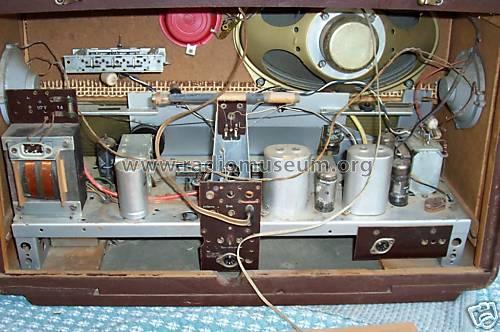
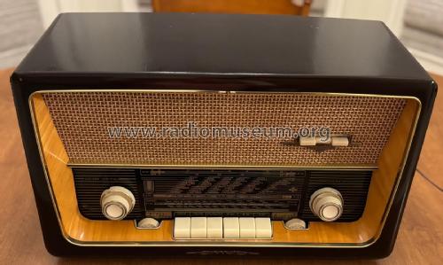
Top View
eBay seller castnowfishing


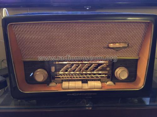
Found in antique store and purchased for $70


Cabinet, back

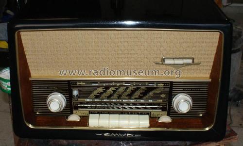
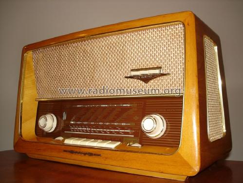
Cabinet, front
Cabinet front, high

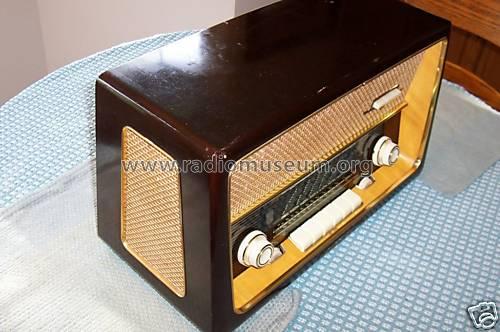
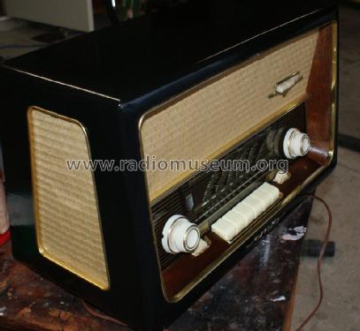
Cabinet, left

Cabinet, right

Chassis, top

Output transformer, side

Output transformer, top

Wiring, bottom center

Wiring, bottom left

Wiring, bottom right
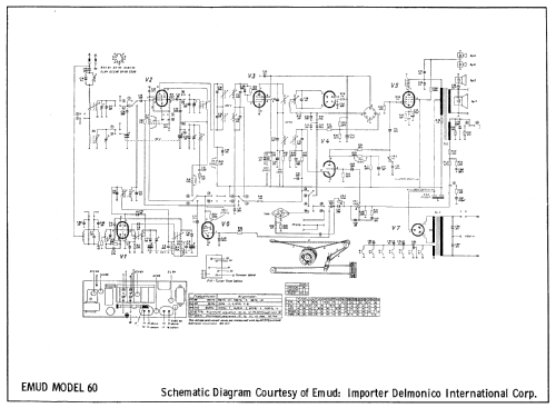
Click on the schematic thumbnail to request the schematic as a free document.
- Number of Tubes
- 7
- Main principle
- Superheterodyne (common); ZF/IF 460/10700 kHz; Export model
- Tuned circuits
- 6 AM circuit(s) 10 FM circuit(s)
- Wave bands
- Broadcast, Short Wave plus FM or UHF.
- Power type and voltage
- Alternating Current supply (AC)
- Loudspeaker
- 4 Loudspeakers
- Power out
- 6 W (unknown quality)
- Material
- Wooden case
- from Radiomuseum.org
- Model: Rekord-Senior 60 [Export] - Emud, Ernst Mästling; Ulm
- Shape
- Tablemodel with Push Buttons.
- Dimensions (WHD)
- 530 x 320 x 250 mm / 20.9 x 12.6 x 9.8 inch
- Notes
-
The model Emud Rekord-Senior 60 Export from Ernst Mästling, Ulm, Germany is nearly the same as the domestic version but it has no long waves. Broadcast is 550 to 1500 kc, short waves from 5.9 to 10 mc and FM from 88 - 108 mc.
Similar with German Emud model Rekord Senior 60.
- Net weight (2.2 lb = 1 kg)
- 9.3 kg / 20 lb 7.8 oz (20.485 lb)
- Literature/Schematics (1)
- Photofact Folder, Howard W. SAMS (Date 12-60, Set 511)
- Literature/Schematics (2)
- -- Original-techn. papers.
- Author
- Model page created by Ernst Erb. See "Data change" for further contributors.
- Other Models
-
Here you find 423 models, 329 with images and 231 with schematics for wireless sets etc. In French: TSF for Télégraphie sans fil.
All listed radios etc. from Emud, Ernst Mästling; Ulm
Collections
The model Rekord-Senior is part of the collections of the following members.
Forum contributions about this model: Emud, Ernst Mästling: Rekord-Senior 60
Threads: 5 | Posts: 40
Hi there! This forum is always so helpful and I'm hoping someone can help me again!
Fiftenn years ago I restored an Emud Rekord Senior 60....lovely radio, really sounds wonderful with classical music especially. Full recap, retube (several had shorts), replaced out of spec resistors, etc. About 5 years ago it bit the dust and as I was moving/getting married/had a kid in those last 5 years, I've not had a chance to look at it since. So taking some time to resurrect it now.
When it died... I just turned it on, while warming up there was a bright pulsing flash & pop just behind the glass near the volume pot. I course I immediately turned it off and didn't power it on again until I started working at it recently. I've done necessary switch cleaning, etc. I found one resistor (R38 I believe) had blown in the area behind the volume pot. I replaced that.
The radio will power (lamps and tubes light), but no sound whatsoever. The only inkling of sound I get is a very faint "pop" when switching bands. I did take some measurements on B+ voltages, both high...at V7 (EZ80) checking about 380v instead of 280v, and at V5 (EL84) checking 380v instead of 270v. I've poured over the connections looking for shorts. Aside from liffting resistors, I'm lost on what this could be. Anyone have an idea where I can start? Thank you!
John Phelps, 01.Mar.25
I just completed a restoration of my 3rd Emud Senior 60 radio. I couldn't resist the twenty-five dollar yard sale cost. It turned out to be the most challenging restoration I've done since I bought a radio that was in a flood and was full of silt.
Electronicaly, I knew there would be a power supply problem because someone had inserted a 20 amp AGC fuse in place of the .8 that should have been there. I guess they didn't have a penny to use! :) As usual the multielemet filter cap was bad but since someone just used larger and larger fuses the power transfomer was fried, The EZ80 tube socket was arced out, the contacts in the on/off switch were burnt off and the wires leading to it were burnt toaster wire. At is point I considered cannibalization!
Fortunately, I had an old transfrmer to replace the burnt unit. So I repcapped the radio, replaced the tube socket with a ceramic one and rewired. But what to do about the on/off switch? I hated the idea of adding an external switch or inline; so I added an "L" bracket on the inside of the back of the chassis with a long lever microswitch; the lever positioned directly behind the sliding wafer board that use to hold the power contacts. There is just enough of the board protruding from the back of the push button assembly to depress the lever when the power button is actuated.
I'm happy that I didn't scrap the unit, as it turned out, I stripped off the cracked and flaking old black finish revealing a great oak veneer. Lightly sanding it and adding one coat of golden oak stain with three coats of Tung oil, the case is beautiful and the sensitivity and sound are the best of the three I have.
I wanted to share this exerience with those who may just be starting out in restoration of these great old radios. Don't get discouraged and don't be afraid to re-engineer around a problem. Once you get them back to specs they sound really great and you'll hate to turn them off and go to the next project!
Earl Roberts, 26.Apr.14
Gentlemen,
While performing capacitor replacement and circuit tracing to verify connections, I noticed that the Output Transformer (OT) connections have been modified beyond recognition. The OT looks just like other EMUD OT's I have found in the model pages, but may have undergone repair or modification during its past lifetime.
A tone cap that should be mounted on the tone switch assembly has been moved to the OT. I would like to re-install in its correct location, but unsure which contacts and what value to place here.
The feedback circuit from the OT to the volume control is completely missing, all resistors and caps that should be located on the OT solder lugs are missing, and no feedback connection to the volume control. It appears to have been connected Single Ended as the Primary CT(B+) and R39 are connected together at the OT. I have inspected the OT and found two taps for the primary and 3 for the secondary, but it doesn't look like it has enough to make all the correct connections required by the schematic.
The photo shows the seconday winding and the some of the lug connections.
Any help in this matter would be greatly appreciated.
Attachments
- EMUD OT (80 KB)
Mark Saltzman, 21.Nov.10
Hi everyone!
I am restoring an EMUD Rekord Senior 60 (US Export), and I have replaced all the paper caps and filter caps. The radio worked well on FM, but was very sketchy on AM/SW bands. Then all of a sudden, it totally stopped working.
I replaced all the tubes, and still nothing. I believe its a problem with one of the IF transformers or a resistor but I am not sure. Pilot lamps light, and tubes glow so I know they're getting power. Does anyone have any suggestions where to look, what to look for?
Thanks for all your help!
John
John Phelps, 25.Jan.09
Hello all...
I'm currently working on an Emud Rekord Senior 60 (export model) and need some assitance. I've replaced the known bad/weak tubes, replaced the 3 electrolytic filter capacitors and all of the paper capacitors, and the is radio close to being electronically restored.
However, I am having a problem with the AM/SW section of the radio. FM band works fine, lots of frequency response, nice and crisp, however the frequency alignment is off about 1mHz. The problem is that both the AM & SW bands are very very low in terms of volume. Sensitivity is also not very good, as it will only pickup the local stations and even has trouble doing that. Antenna seems to be connected okay. Anybody have an idea as to if this is a tube problem or something else? I'm thinking it could be a tube though I'm not sure which one, as I wasn't able to check them all with my tester (didn't have tube data for 2 of them). I'm stumped on this one. Any help would be GREATLY appreciated!
Thanks!
John
John Phelps, 01.Dec.08