- Country
- Germany
- Manufacturer / Brand
- Grundig (Radio-Vertrieb, RVF, Radiowerke)
- Year
- 1965 ?
- Category
- Broadcast Receiver - or past WW2 Tuner
- Radiomuseum.org ID
- 136863
-
- alternative name: Grundig Portugal || Grundig USA / Lextronix
Ebay 350243624449 Bild bearbeitet.

Ebay 350243624449 Bild bearbeitet.
Ebay 350243624449 Bild bearbeitet.
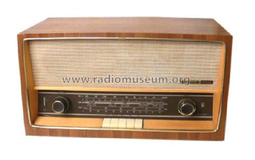
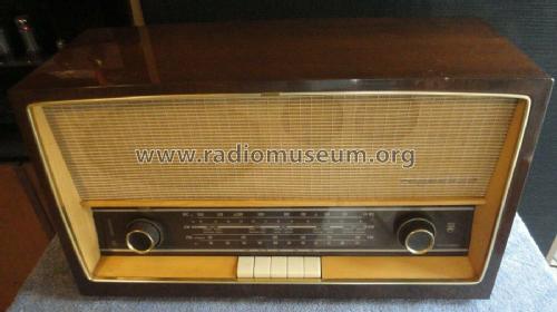
This is another from my own collection.
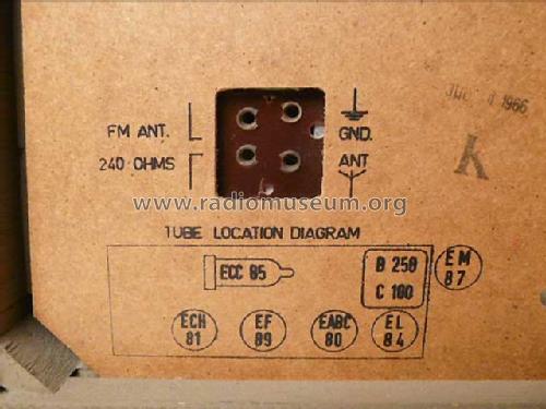
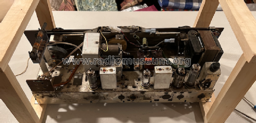
aus ebay, #124006461544, Verkäufer acroman

aus ebay, #124006461544, Verkäufer acroman

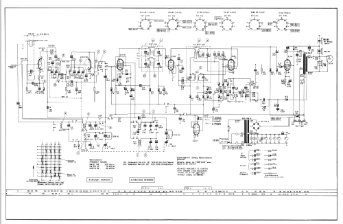
Click on the schematic thumbnail to request the schematic as a free document.
- Number of Tubes
- 6
- Main principle
- Superheterodyne (common); ZF/IF 460/10700 kHz
- Wave bands
- Broadcast, Short Wave plus FM or UHF.
- Power type and voltage
- Alternating Current supply (AC) / 115; 220 Volt
- Loudspeaker
- 3 Loudspeakers
- Material
- Wooden case
- from Radiomuseum.org
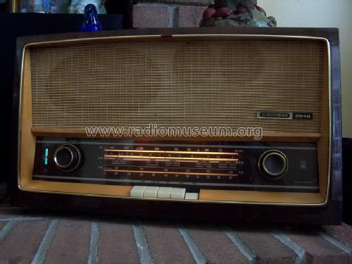
- Model: 2540U - Grundig Radio-Vertrieb, RVF,
- Shape
- Tablemodel with Push Buttons.
- Dimensions (WHD)
- 550 x 320 x 225 mm / 21.7 x 12.6 x 8.9 inch
- Notes
- Exportgerät für USA
- Mentioned in
- -- Original prospect or advert
- Author
- Model page created by Walter Groer. See "Data change" for further contributors.
- Other Models
-
Here you find 6196 models, 5420 with images and 4190 with schematics for wireless sets etc. In French: TSF for Télégraphie sans fil.
All listed radios etc. from Grundig (Radio-Vertrieb, RVF, Radiowerke)
Collections
The model is part of the collections of the following members.
Forum contributions about this model: Grundig Radio-: 2540U
Threads: 3 | Posts: 17
I have been restoring my Grundig 2540U. After replacing all the electrolytic and paper capacitors it was working but the volume would start out loud with full closure of the magic eye then after about 5 seconds the eye would open and the volume would drop down. Occasionally, when listening to FM for a while, the volume would suddenly increase for several seconds then drop down again.
After reviewing the schematics I realized that the PU/TR button when in the off position (not pressed) closes a switch that provides B+ to the magic eye, ECC85 and ECH81. I realized that I almost never pushed the PU/TR button since I have no aux. setup. After working the PU/TR button numerous times the intermittent volume problem has resolved. The FM, AM and SW volume is markedly improved. The magic eye closes and there is no intermittent volume change.
My question. Is it possible that I cleaned the contacts on the PU/TR button by pushing it and exercising it? How are people cleaning the push button switches on these German radios since they are difficult to see inside of the switch box?
Thanks
Peter
Peter DeLuca, 31.Mar.22
I wanted to upload a PDF of the schematic but can't. If some one needs it email me zenith6@verizon.net
Louis deGonzague, 13.Dec.19
Hello Radiophiles,
I have just restored a Grundig 2540U that has been in my extended family since it was bought around 1965.
Most of the restoration consisted in cleaning tube socket and switch contacts with Deoxit.
The power switch was stuck, but some wd-40 free it up, and it works fine now.
I thought I was all done, until the FM would come in and out,intermittently. It would get very soft, but not dead, then it would suddenly get loud again.
Some circuit tracing narrowed the problem down to the ratio detector transformer. I used the schematic for the 2420U,2440U as a guide because these models are similar and I could not find a schematic for the 2540U
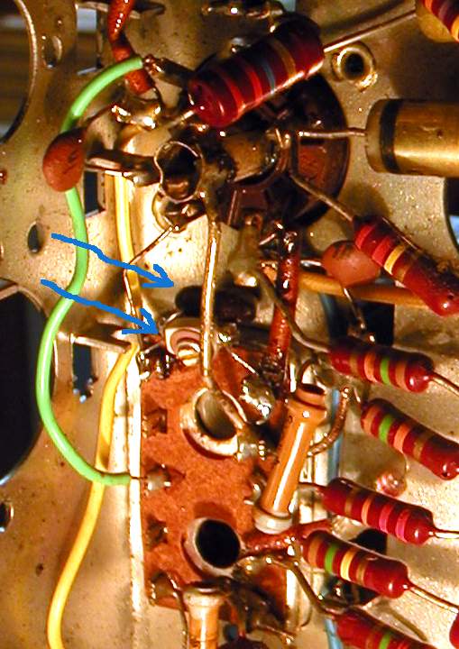
 The 56pF 2.5% Polystyrene capacitor that resonates with the secondary of the Ratio transformer had developed an intermittent between it's tinned wire leads and the aluminium foil.
This cap is normally installed inside the Ratio transformer can, but was actually visible through an opening at the bottom of the can.
The cap is shown here with one leg already disconnected, and partly removed from the can.
I used a pair of long scissors to avoid taking the transformer appart to cut the cap end open.
The can you see in the photo is the bottom half of the IF transformer shield. The top half slips over the top. The bottom half can't be removed without disconnecting all the transformer wires.
After disconnecting one leg of the intermittent Polystyrene cap, I tucked it back in place, to document it as the original.
 Then I added a 39pF mica capacitor and a NPO ceramic trimmer cap with a 5-50pF trim range.
The ceramic trimmer was soldered directly on the legs of the 39pF mica cap before wiring to the bottom terminals of the transformer.
I realigned the new trim cap by recentering the ratio detector voltage, which was very well centered when the polystyrene cap was working.
The ratio detector voltage is centered, or nulled, when the difference between the detector audio output voltage and half of the voltage across the electrolytic cap in the detector is zero. The half voltage of the electrolytic cap is usualy obtained by isntalling a couple of 100k resistors, but in this case a series pair of 15k resistors was already wired across the electrolytic cap.
This is the third intermittent PolyStyrene capacitor I have had to dig out of the IF transformer cans of German AM-FM radios. The other two cases were the middle FM IF transformer of a Grundig 87-USA, and the middle FM IF transformer in a Olympic-Kobold 5720W.
All three of these sets showed the same sporadic drop in FM output, that could sometimes be brought back by switching bands. The band switching would cause an electric spike that would bridge the connection temporarily.
Regards,
-Joe
Joe Sousa, 17.Aug.09