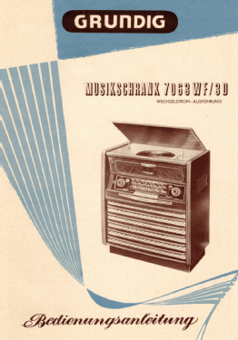
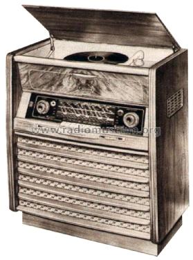
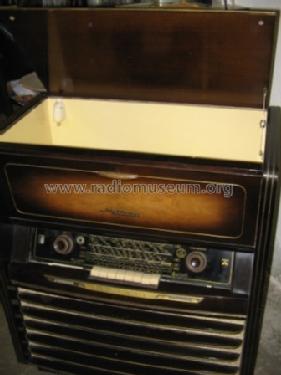
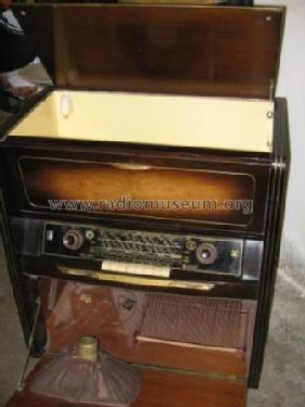
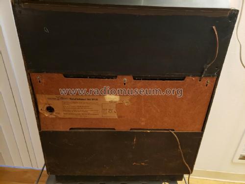
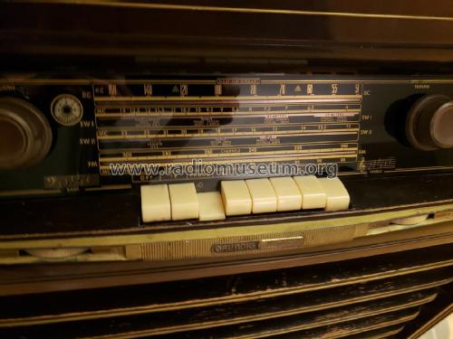
Musikschrank 7063WF/3D
Grundig (Radio-Vertrieb, RVF, Radiowerke)
- Country
- Germany
- Manufacturer / Brand
- Grundig (Radio-Vertrieb, RVF, Radiowerke)
- Year
- 1955/1956
- Category
- Broadcast Receiver - or past WW2 Tuner
- Radiomuseum.org ID
- 104130
-
- alternative name: Grundig Portugal || Grundig USA / Lextronix
Lange

Lange


Q: Grundig, Produkt-Katalog '55

Q: Grundig, Produkt-Katalog '55

Click on the schematic thumbnail to request the schematic as a free document.
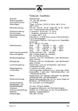
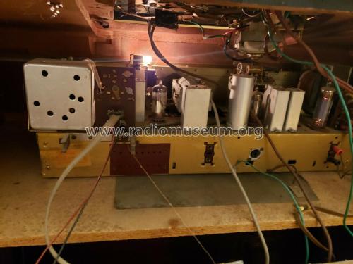
- Number of Tubes
- 6
- Main principle
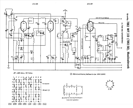
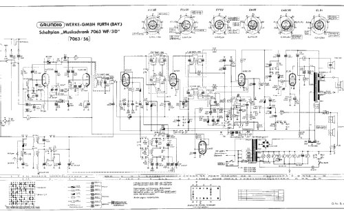
- Superheterodyne (common); ZF/IF 468/10700 kHz; 2 AF stage(s)
- Tuned circuits
- 6 AM circuit(s) 9 FM circuit(s)
- Wave bands
- Broadcast, Long Wave, Short Wave plus FM or UHF.
- Details
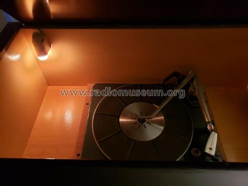
- Changer (Record changer)
- Power type and voltage
- Alternating Current supply (AC) / 110; 125; 160; 220 Volt
- Loudspeaker
- 4 Loudspeakers
- Material
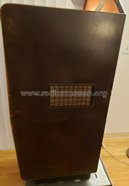
- Wooden case
- from Radiomuseum.org
- Model: Musikschrank 7063WF/3D - Grundig Radio-Vertrieb, RVF,
- Shape
- Console with Push Buttons.
- Source of data
- Guida Pratica Antique Radio III (2000)
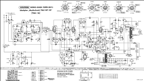
- Literature/Schematics (1)
- Lange, Schaltungen der Funkindustrie
- Author
- Model page created by Walter Wiesmüller † May 2012. See "Data change" for further contributors.
- Other Models
-
Here you find 6196 models, 5420 with images and 4190 with schematics for wireless sets etc. In French: TSF for Télégraphie sans fil.
All listed radios etc. from Grundig (Radio-Vertrieb, RVF, Radiowerke)
Collections
The model Musikschrank is part of the collections of the following members.
Forum contributions about this model: Grundig Radio-: Musikschrank 7063WF/3D
Threads: 1 | Posts: 9
I'm restoring this model and could use your help.
I've replaced paper and electrolytic capacitors and tested all tubes but I'm still having two key problems.
1. When tuning the AM broadcast band, signals whistle and oscillate. Fine tuning sometimes clears it up, but adjusting the treble control which moves a ferrite rod into (an IF coil?) usually does the trick. What might be wrong here?
2. The FM band is distorted, even with an external antena connected, through most of the dial but is clear on one or two strong stations. Is it just in need of a tuning?
Thank you for any help you can provide.
Tom Ragan, 06.Mar.08