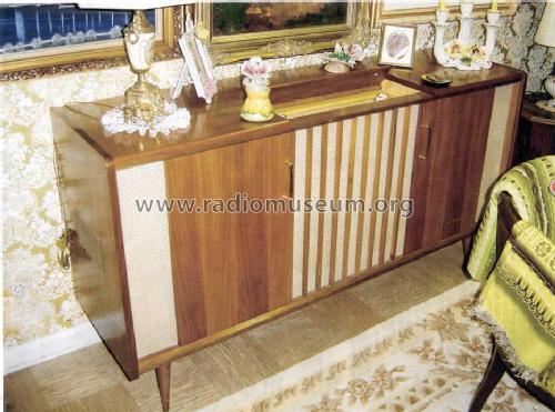
Stereo Console SO390-U/S
Grundig (Radio-Vertrieb, RVF, Radiowerke); Fürth/Bayern
- Pays
- Allemagne
- Fabricant / Marque
- Grundig (Radio-Vertrieb, RVF, Radiowerke); Fürth/Bayern
- Année
- 1962/1963
- Catégorie
- Radio - ou tuner d'après la guerre 1939-45
- Radiomuseum.org ID
- 102341
-
- alternative name: Grundig Portugal || Grundig USA / Lextronix


Cliquez sur la vignette du schéma pour le demander en tant que document gratuit.
- No. de tubes
- 14
- Principe général
- Super hétérodyne (en général)
- Circuits accordés
- 8 Circuits MA (AM)
- Gammes d'ondes
- PO, 2 x OC et FM
- Particularités
- Tourne disque avec changeur
- Tension / type courant
- Alimentation Courant Alternatif (CA) / 115/220 Volt
- Haut-parleur
- 6 HP
- Matière
- Boitier en bois
- De Radiomuseum.org
- Modèle: Stereo Console SO390-U/S - Grundig Radio-Vertrieb, RVF,
- Forme
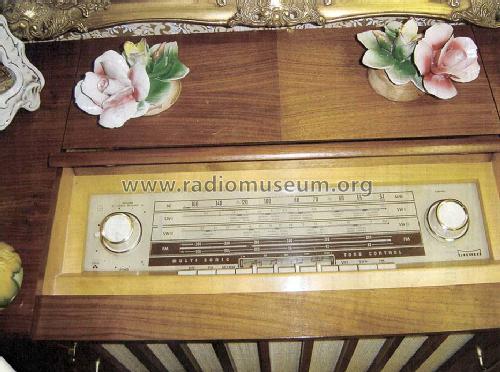
- Console avec des boutons-poussoirs
- Remarques
- This model is with its full name a Grundig export version for the USA: "Stereo Console 390 U/S" with a FM-Stereo Decoder and a Stereo Amplifier NF2 (2 x ECC83 and 4 x EL84). The back wall indicates 115 volts AC only but the set is for 115/220 Volts. Power consumption 110W plus Record Changer 7.5 Watt. Pilot Bulbs 7 V/0.3A. Push Buttons are for selecting OFF,PU,BC/MW,SW1,SW2,FM and STEREO,JAZZ,MULTUSONIC,ORCH,FA/AFT.
- Littérature
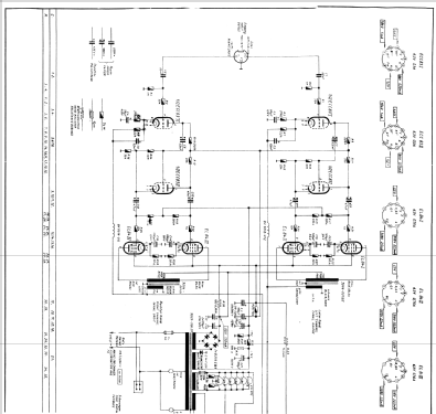
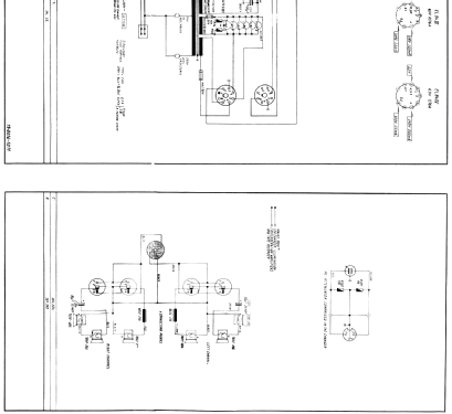
- -- Schematic
- Auteur
- Modèle crée par Franz-Josef Haffner. Voir les propositions de modification pour les contributeurs supplémentaires.
- D'autres Modèles
-
Vous pourrez trouver sous ce lien 6250 modèles d'appareils, 5496 avec des images et 4249 avec des schémas.
Tous les appareils de Grundig (Radio-Vertrieb, RVF, Radiowerke); Fürth/Bayern
Contributions du forum pour ce modèle: Grundig Radio-: Stereo Console SO390-U/S
Discussions: 1 | Publications: 7
hi,
i inherited this console fron my grandfather, Te power transformer was shot, because the filter caps failed, and someone put a wire in the fuse.
I sent the trasformer to repair it, but the technician dissapeared with the transfomer.
the console sat for years collecting dust in my house, and now i decided to finish the repair.
i will make a full recap and change the selenium rectifiers.
i started collecting info about it to figure out the specs of the transformer.
i found the schematic for the amplifier(NF2) and with this info i figured out some specs
For the B+:
312V[A*T]150Ma after rectifier.
312/1.44=217
first tap= 220V[A*T]150mA, but to be sure 220V[A*T]250mA.
If i consider the transformer regulation then 240V[A*T]250mA
For heaters the transformer have 2 windings:
first one for tubes in amp section and dial lamps.
The consumption for all tubes is around 4A
so this winding is 6,3V 4A
second one for tubes in pre/tuner section:
the consumption for all tubes is around 3A
So This winding is 6,3V[A*T]3A.
For bias
-16V after rectifier.
then it is adjusted with resistors to -11V
so this winding is 12V[A*T]30mA
so far so good, but then i came across the sams photofact for this model and the values are not the same for b+
the specs for the transformer are the following:
Secondary 1: 320V[A*T]150mA
secondary 2: 6,3V[A*T]2,4A
secondary 3: 6,3V[A*T]4A
secondary 4 15V[A*T]20mA.
also lists 330V after rectifier.
i'm a little confused. 320VAC is way to high even to get 330V after rectifier and considering the loss in selenium rectifiers and transformer regulation.
also i think 150 mA is too little.
i'm missing something?
also i'm curious about output trannies.
the sams photofact lists the following
primary: 5Kohms CT
secondary 3-4 ohms
i think 5K ist too little for 2 el84 Push-pull.
maybe is 5k between plate and center tap?, so the transformer is 10K?
Alfonso López-Martínez, 11.Feb.12